background image


Grinding Tapered Cutters- 

  Circular Grinding of side and End Cutting Edges 

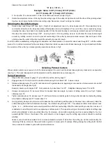
Tapered cutters can be ground to size in the machine without the use of any measuring instrument, except for the scales provided on 

the machine. For circular grinding operations on profiled cutters follow this procedure: 

Setup Operations 

1. 

Align cutter lip by means of gauge ’C; grip cutter in position; return gauge C. 

2. 

Draw index pin P out of slot hole to enable collets bearing to be rotated through 360

o

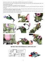
 Release clamping levers T2, T3, T6. Set 

scale S2 and F at zero. Tighten clamping levers T4, T2, T3, T6 see Fig. 

3. 

Release clamping lever T7;bring cutter diameter into light contact with grinding wheel; tighten clamping lever T7,taking care to 

keep index mark of vertical swivel mount aligned with tubular guide; release clamping lever T4,see Fig.4. 

4. 

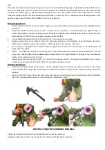
A.N0.5 profile 9Fig. 1 and 2): Release clamping lever T1; rotate knurled knob S4 to shift cross slide to the right by one-half of 

dialog the taper (‘Fig.1). For this purpose use cross slide venire scale T. Tighten clamping lever T1. 

B.No.6 profile (Fig. and 2): Release clamping lever T1; rotate knurled knob S4 to shift cross slide to the right by the desires 

amounts” (use cross slide venire scale T). Tighten clamping lever T1. 

C.No.7 profile (Fig. 1 and 3): Set cross slide venire scale at zero. 

5. 

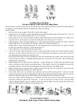
A.No.5 and 7 profiles: Rotate fine adjustment screw H to bring cutter diameter into light contact with grinding wheel: again 

rotate screw H to shift cutter to the left by amount x = D/2-a. To facilitate this setting operation, set scale drum of screw H at 

zero without disturbing the setting of the screw (see Fig.4). 

b.No.6 profile :Rotate screw H to bring cutter diameter into light contact with grinding wheel; again rotate screw H to shift cutter 

to left by the amount x=D/2-(a+r). To facilitate this setting operation, set scale drum of screw H at zero without disturbing the 

setting of the screw (see Fig.4). 

6. 

Release clamping lever T3; ratate swivel arm through 90

o

    ; release clamping lever T5; rotate index head slide micrometer 

screw S to advance end face of cutter towards grinding wheel.    Wheel tapered cutters are to be retargeted; the length of the 

cutting edge at the end of the cutter should be made greater than the small diameter of the tapered portion. 

7. 

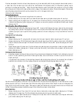
Release clamping lever T6; hold index drum F against its stop and counting from the zero position, set swivel arm at the 

desired taper angle; tighten clamping lever T3 and T6, sgg Fig.6. 

8. 

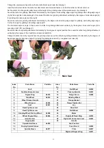
A.No.5 profile: Slowly return stop screw Gad and continuously rate the collets bearing through 360

o

    to advance the cutter 

past the grinding wheel. Prior to the circular grinding operation ratite fine adjustment screw H to shift the cutter to the right; the 

advance the cutter towards the wheel by small increment unit the desired size has been obtained (see Fig.6). 

b.No.6 and 7 profiles: Release clamping lever T3; first slowly return stop screw G, then slowly swing the swivel arm while 

continuously rotating the collets bearing through 360

o

  to move the cutter past the wheel and thus to circular grinding 

operation ratite fine adjustment screw H to shift the cutter to the right; then advance the cutter towards the wheel by small 

increments until the desired size has been obtained (see Fig.7 & 8). 


Circular Tapered Cutters- 

Grinding the Back Angle of Side and End Cutting Edges 


6

Содержание 426245

Страница 1: ...GRINDER OWNER S MANUAL WARNING Read carefully and understand all INSTRUCTIONS before operating Failure to follow the safety rules and other basic safety precautions may result in serious personal inj...

Страница 2: ...nt set screw S2 Vertical swivel mount setting scale S4 Index head slide fine adjustment screw T2 Vertical swivel mount clamping lever Q Cross slide T3 Horizontal swivel mount clamping lever T6 Index d...

Страница 3: ...t off index drum F to pull out adjusting nut and screw U2 rotate screw 180o relative to nut to reduce the length to reassemble parts reverse procedure Adjusting the stop pin for the 90o swivel motion...

Страница 4: ...of less than 20o should be relief ground at between 25 o and 30 o Cutter Speeds As regards single lip milling cutters it is recommended to use cutting speeds three times higher than those used with s...

Страница 5: ...set the index head accurately relative to the wheel and to provide the desired depth of cut The travel of the cutter past the wheel can be limited by means of adjustable stop screw G Thus it is possib...

Страница 6: ...ing of the side cutting edge or it may be ground independently In the latter case the cutter will have to be aligned by means of gauge Cad clamped in position Whenever a single lip cutter is to be gro...

Страница 7: ...ed to suit the material to be cut see page 5 Setup Operations 1 Align cutter lip by means of gauge C grip cutter in position return gauge C 2 Engage index pin P into short slot to enable collets beari...

Страница 8: ...without disturbing the setting of the screw see Fig 4 b No 6 profile Rotate screw H to bring cutter diameter into light contact with grinding wheel again rotate screw H to shift cutter to left by the...

Страница 9: ...tion set swivel arm at the desired angle for example where an angle of 10 is desired the swivel arm will have to be set at 80 Tighten clamping levers T3 and t see Fig 4 3 Tighten clamping lever T4 rel...

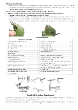
Страница 10: ...DARD EQUIPMENT 1 Wheel dresser with diamond 1 14 Wheelmount Flange C1 1 2 Diamond pen 1 15 Hock spanner C8 1 3 Wheel mount Flange C1 1 16 Wheellockpin C5 1 4 Driving belt C3 1 17 Springcollects C7 5 1...

Страница 11: ...K5 Release clamp 3 on attachment and adjust swivel mounted V guide 4 until the scale shows the diameter of the twist 5 Drill to be ground Retighten clamp 3 Release clamp K1 tighten clamp K Move index...

Страница 12: ...ide pin to grinding the rake of end mill following the screw of end mill by the direction from front to back as drawing IV To grinding the secondary relief angle when the primary relief angle grinding...

Страница 13: ...ivel the lathe tool grinding attachment horizontally by the degree at original position then swivel the lathe tool grinding attachment vertically by the degree of front relief E and second relief E2 C...

Страница 14: ...ht Left Fixed Screw 20 Collect A4001 8 Key 21 Key 9 Right Left Micro Adjust Level 22 Seat A3003 10 Gear A4005 23 Handle 11 Plate A4038 24 Turning Seat A3006 12 Dearer Bolt A4030 25 Sleeve Tighten Nut...

Страница 15: ...Bolt M6 12 9 Bolt M4 8 5 13 Bolt A4031 M6 20 End Mills Attachment Index NO Parts Name Parts NO Remarks Index NO Parts Name Parts No Remarks 1 Collect seat Tighten Screw A4019 9 Bolt M5 12 2 Collect Se...

Страница 16: ...Northern Tool Equipment Co 2800 Southcross Drive West P O Box 1499 Burnsville MN 55337 0499 Made in China...

Отзывы: