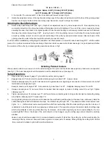
avoid inflammation.
Tool angles recommended cutting speeds for single-lip cutters
Centering the Cutter Lip by Grinding
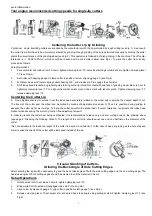
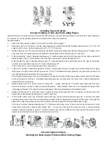
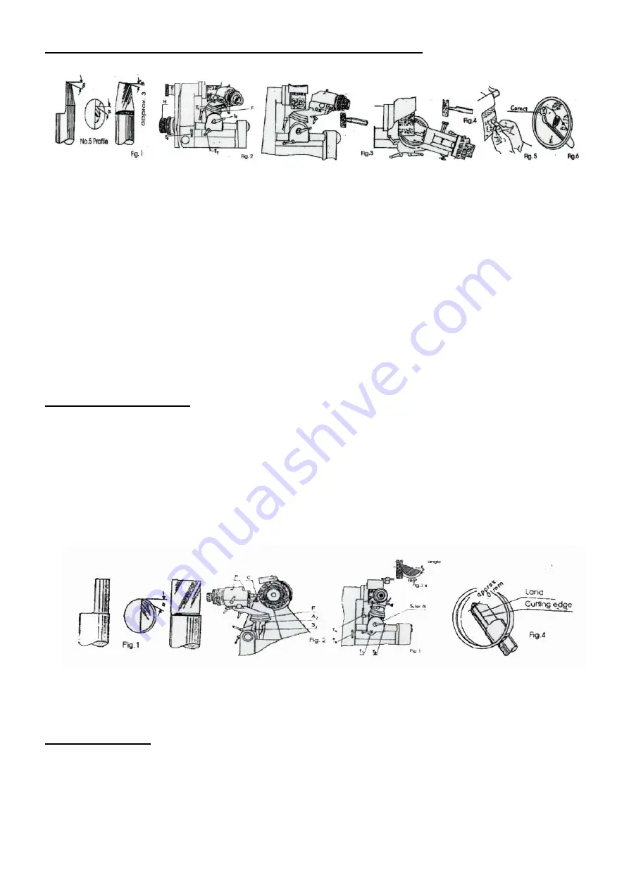
Cylindrical single-lip milling cutters are supplied by the manufacturer with the lip preformed by rough milling (see Fig. 1). As a result,
the cutter lip will first have to be accurately centered by grinding. Rough grinding of the lip is performed manually by holding the cutter
giants the circumference of the grinding wheel (see Fig.2). This operation is followed by finish grinding in the machine. The off center
tolerance is
±
.0004”(0.01mm), which should be checked with a micrometer caliper (see Fig.3). To grind the cutter lip correctly,
proceed as follows:
Setup Operations
1.
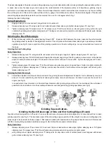
Set swivel arm and index drum F at zero, tighten clamping lever T3: set vertical setting scale S2 at zero, tighten clamping lever
T2 (see Fing.4).
2.
Set cutter with aligning gauge C clamp cutter in position, rectum aligning gauge C (see Fig.6).
3.
Withdraw index pin Prostate spring collect bearing 180
o
, allow index pin P to engage the short-slot.
4.
Shift index head bracket along tubular guide to bring cutter lip into light contact with end face of grinding wheel. Be sure prior to
tightening clamping lever T7, to align vertical sisal swivel mount index mark with tubular guide. Tighten clamping lever T7,
release clamping lever T4.
Centering the Cutter Lip
6. Fine adjustment screw H serves to set the index head accurately relative to the wheel and to provide the desired depth of cut.
The travel of the cutter past the wheel can be limited by means of adjustable stop screw G. Thus it is possible, during priding to
advance the cutter as far as it will go. To bring the cutter lip within the prescribed off-center tolerance, reciprocate the index head
bracket while advancing the cutter by rotation fine adjustment screw H.
In order to prevent the cutter from being overheated, it is recommended to leave only a narrow cutting zone on the grinding wheel
(see page 5 “Dressing the Grinding Wheel”). The length of the cutter lip should equal one and one half times the diameter of the
cutter.
It is not advisable to Increase the length of the cutter lip beyond a certain limit. In the case of deep engraving work where stepped
cutter is sued the shank of the cutter will be increased instead of the lip.
Circular Grinding of Cutters-
Grinding the Back Angle of Side Cutting Edges
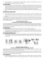
After centering the lip it will be necessary to grind the back rake angles of both the side cutting edge and the end cutting edge. The
back rake angles of both cutting edges should be selected to suit the material to be cut.
Setup Operations
1.
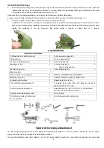
Rotate swivel arm to set index F at zero; tighten clamping lever T3.
2.
Bring white dot into window Unengaged index pin P into long slot.
3.
Align cutter by means of gauge C; grip cutter in position return gauge C (see Fig.2).
4.
Release clamping lever T2;set swivel arm at desired back rake angle using setting scale S2;tighten clamping lever T2 (see
Fig.3).
3


