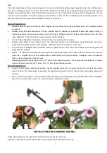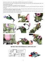
Grinding the Back Rake Angle
3.
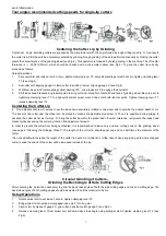
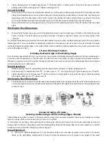
While continuously rotating the collets bearing through 180 (back and forth between the stops), advance the cutter towards the
grinding wheel by means of fine adjustment screw H. This will produce the desired back rake angle on both side and the end
cutting edges in a positively controlled operation (see Fig.3, 4, 5).
Upon completion of grinding operations, a very narrow land must remain at the cutting edge.
In cases where the cutter is intended for the machining of hard steel which requires a small back rake angle, it is
4.
Advisable to grind off part of the curvature in a manual operation (see Fig.6).
In addition it is recommended, with regard to all single lip cutters, to whet also the cutting lip by means of an oil stone in order to
remove burrs. However, care should be exercised not to remove noticeable amount of stock from the cutting lip, as this would
destroy the centering of the lip; moreover, this would render a greater or lesser part of it useless.
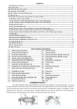
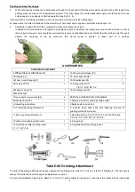
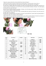
ACCESSORIES
STANDARD EQUIPMENT
1.Wheel dresser with diamond 1
14.Wheelmount(Flange)(C1) 1
2.Diamond pen 1
15. Hock spanner(C8) 1
3.Wheel mount(Flange)(C1) 1
16.Wheellockpin(C5) 1
4.Driving belt (C3) 1
17.Springcollects(C7) 5
1/8’,1/4”,5/16”,3/8”,1/2”
5.Wheel lock pin(C5) 1
18.Wheelspanner(C9) 1
6.Machine light 1
7.Hex socket screw wrench(C4) 4
SPECIAL ACCESSORIES (ON EMEND)
8.Aligning finger(C6) 1
1.Diamond wheel for grinding carbide cutter
9. Operating Instructions 1
2.Balance stand and arbor
10. Twist drill grinding attachment 1
3. Special index head slide with clamping sleeves for
grinding dial,20,25mm cutter
11.End mill grinding attachment 1
4.R8collets:dia, 3,4,5,6,8,9,10,12,14,16,18,20,22,25and
1/8’,3/16”,1/4”,5/16”,3/8”,1/2”,5/8”,3/4”
12.Lathe tools grinding attachment 1
5. Driving belt.
13. High-speed cutter grinding wheel 1
6. High-speed cutter grinding wheel.
4”
×
2”
×
3/4”(C2)
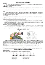
Twist Drill Grinding Attachment
The twist drill grinding attachment has been designed for grinding twist drills of 3 to 18 mm (1/8”to11/16”)diameter. The lip angle is
always 116, while the back rake angle is adjustable as required.
8
To mount the attachment (see Fig.2), attach a 12 mm (1/2”) spring collets to locating pin 1 and insert the collets into the index head


