


Chapter 2 Installation
57
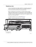
Installing the Breaker Interface Panel for the Ethernet Routing Switch 8010co Chassis
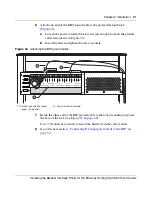
6
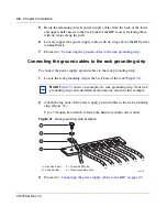
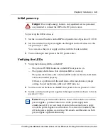
Connect the A/B input feed returns.
a
Locate the A/B Input Feed Returns section of the power terminal block.
b
Loosen one of the four available A/B input feed return connection screws
just enough to insert the cable lead (item 1 in
Figure 39
).
You can use any of the four available input feed return connections.
c
Insert the lead and tighten the screw securely.
Figure 39
Connecting the A/B input feed returns (1 of 2)
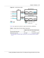
Note:
The total number (quantity) of Input feed return cable leads must
match the total number of Input feeds used for your installation.
10408FA
3 2
PS (+)
Lower Shelf
PS (+)
Upper Shelf
PS (-)
Lower Shelf
PS (-)
Upper Shelf
A/B Input Feed
Returns
– 48 VDC
A/B Input Feeds
1 3 2 1
3 2 1 3 2 1
A
2
A
1
B
1
B
2
1 = -48 VDC input feed Return (Primary A feed Return)
2 = -48 VDC input feeds (Primary A, Secondary A, Primary B, Secondary B)
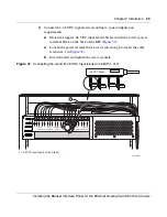
-48 VDC Feeds
Return A feed 1
1
2
Содержание 8010co
Страница 6: ...6 312755 G Rev 00...
Страница 10: ...10 Contents 312755 G Rev 00...
Страница 14: ...14 Tables 312755 G Rev 00...
Страница 18: ...18 Preface 312755 G Rev 00...
Страница 66: ...66 Chapter 2 Installation 312755 G Rev 00...