


Chapter 1 Overview
27
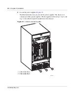
Installing the Breaker Interface Panel for the Ethernet Routing Switch 8010co Chassis
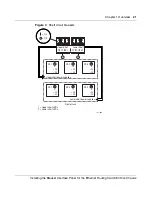
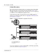
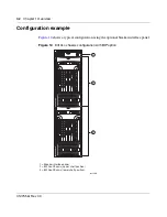
This type of configuration allows you to independently monitor and control the
external audible and visual alarm status indications of the BIP at the central office.
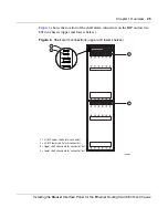
Figure 8
Configuring standalone BIPs to report alarm status
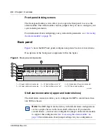
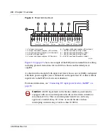
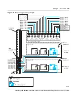
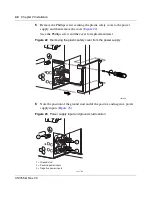
Power terminal block
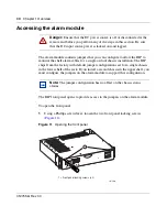
The power terminal block is located on the back panel of the BIP. As shown in
Figure 9 on page 28
, the power terminal block provides 21 connection blocks for
DC input and output feeds.
3 2
PS (+)
Lower Shelf
PS (+)
Upper Shelf
PS (-)
Lower Shelf
PS (-)
Upper Shelf
A/B Input Feed
Returns
– 48 VDC
A/B Input Feeds
1 3 2 1
3 2 1 3 2 1
A
2
A
1
B
1
B
2
3 2
PS (+)
Lower Shelf
PS (+)
Upper Shelf
PS (-)
Lower Shelf
PS (-)
Upper Shelf
A/B Input Feed
Returns
– 48 VDC
A/B Input Feeds
1 3 2 1
3 2 1 3 2 1
A
2
A
1
B
1
B
2
3 2
PS (+)
Lower Shelf
PS (+)
Upper Shelf
PS (-)
Lower Shelf
PS (-)
Upper Shelf
A/B Input Feed
Returns
– 48 VDC
A/B Input Feeds
1 3 2 1
3 2 1 3 2 1
A
2
A
1
B
1
B
2
J1
J2
J3
J4
J5
10419EA
1 = J5 (standalone office alarm connector)
BIP 1
BIP 2
BIP 3
To central office
To central office
To central office
1
Содержание 8010co
Страница 6: ...6 312755 G Rev 00...
Страница 10: ...10 Contents 312755 G Rev 00...
Страница 14: ...14 Tables 312755 G Rev 00...
Страница 18: ...18 Preface 312755 G Rev 00...
Страница 66: ...66 Chapter 2 Installation 312755 G Rev 00...