


Chapter 1 Overview
31
Installing the Breaker Interface Panel for the Ethernet Routing Switch 8010co Chassis
2
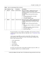
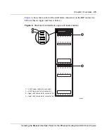
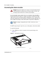
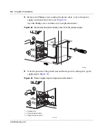
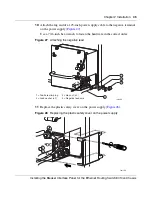
Gently lower the front panel to expose the alarm module (
Figure 12
).
Figure 12
Accessing the alarm module
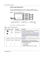
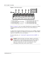
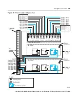
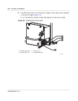
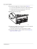
Figure 13
shows a close-up view of the alarm module with jumpers J8 and J9
configured to monitor the shelf alarm cable for a single chassis in the lower shelf
only (default setting). Monitoring of the upper shelf alarm cable is disabled with
jumper J8, by default.
To enable the BIP to monitor the shelf alarm cable for a second chassis in the
upper shelf, you must place the upper shelf alarm jumper (J8) over pins 2 and 3.
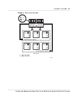
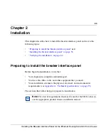
Figure 13
Default jumper settings
10365FB
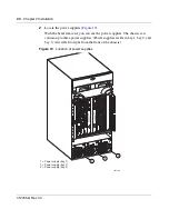
1
1 = Alarm module
1 = Alarm module
2 = J9 Lower shelf alarm jumper (enabled)
3 = J8 Upper shelf alarm jumper (disabled)
1
J9
J8
3 2 1 J9
2
3 2 1 J8
3
10366EB
Содержание 8010co
Страница 6: ...6 312755 G Rev 00...
Страница 10: ...10 Contents 312755 G Rev 00...
Страница 14: ...14 Tables 312755 G Rev 00...
Страница 18: ...18 Preface 312755 G Rev 00...
Страница 66: ...66 Chapter 2 Installation 312755 G Rev 00...