


Chapter 2 Installation
43
Installing the Breaker Interface Panel for the Ethernet Routing Switch 8010co Chassis
7
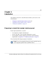
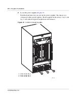
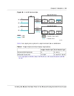
Locate the following items in the shipping container (
Figure 24
).
•
125-inch power cables—for power supplies located in the lower chassis
•
90-inch power cables—for power supplies located in the upper chassis
•
90-inch ground cables—for grounding of power supplies located in the
upper and lower chassis
Figure 24
Power supply cables
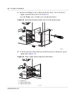
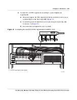
8
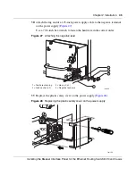
Attach one end of a 90-inch ground cable to the grounding stud on the power
supply. Use a 7/16-inch hex wrench to fasten the hardware in the correct order
(
Figure 25
).
The hardware (washers and nuts) are included with the power supply
shipment.
Figure 25
Attaching the ground lead
10428FC
1
2
3
1 = 125-inch power supply cables (x 6)
2 = 90-inch power supply cables (x 6)
3 = 90-inch power supply ground cables (x 6)
-DC
+DC
10297FA
3
4
5
2
1
1 = Grounding stud
2 = Flat washer
3 = Crimp lug
4 = Lock washer
5 = Hex nut
6 = Earth ground lead
6
Содержание 8010co
Страница 6: ...6 312755 G Rev 00...
Страница 10: ...10 Contents 312755 G Rev 00...
Страница 14: ...14 Tables 312755 G Rev 00...
Страница 18: ...18 Preface 312755 G Rev 00...
Страница 66: ...66 Chapter 2 Installation 312755 G Rev 00...