


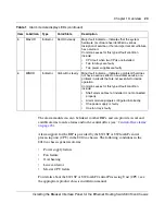


Chapter 1 Overview
25
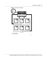
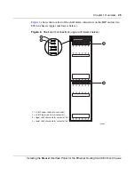
Installing the Breaker Interface Panel for the Ethernet Routing Switch 8010co Chassis
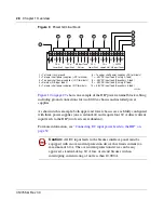
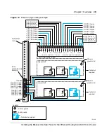
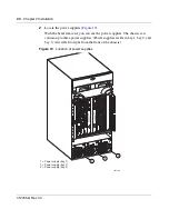
Figure 6
shows the location of the shelf alarm connectors on the BIP and on two
8010co chassis (upper and lower shelves).
Figure 6
Shelf alarm connections (upper and lower shelves)
1 = J1 (BIP upper shelf alarm connector)
2 = J2 (BIP lower shelf alarm connector)
3 = Upper shelf chassis alarm connector "out"
4 = Lower shelf chassis alarm connector "out"
1
2
3
4
J1
J2
J3
J4
J5
10380EA
Содержание 8010co
Страница 6: ...6 312755 G Rev 00...
Страница 10: ...10 Contents 312755 G Rev 00...
Страница 14: ...14 Tables 312755 G Rev 00...
Страница 18: ...18 Preface 312755 G Rev 00...
Страница 66: ...66 Chapter 2 Installation 312755 G Rev 00...