


46
Chapter 2 Installation
312755-G Rev 00
12
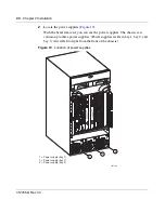
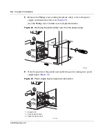
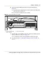
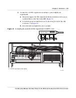
Secure the power supply in bay 1 of the lower chassis (
Figure 29
).
a
Use the power supply handle to push the power supply firmly into bay 1.
b
Push the extractor lever down to lock the power supply in place.
c
Tighten the two power supply retaining screws.
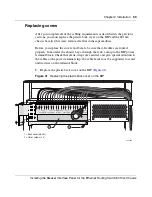
Figure 29
Replacing the power supply
13
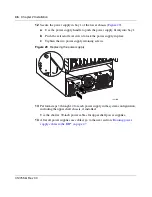
Perform steps
3
through
12
for each power supply in the system configuration,
including the upper shelf chassis, if installed.
Use the shorter, 90-inch power cables for upper shelf power supplies.
14
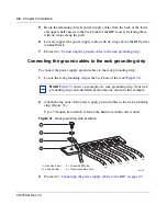
After all power supplies are cabled, go to the next section,
“Routing power
supply cables to the BIP” on page 47
.
10432FB
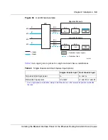
+DC
-DC
+DC
-DC
+DC
-DC
Содержание 8010co
Страница 6: ...6 312755 G Rev 00...
Страница 10: ...10 Contents 312755 G Rev 00...
Страница 14: ...14 Tables 312755 G Rev 00...
Страница 18: ...18 Preface 312755 G Rev 00...
Страница 66: ...66 Chapter 2 Installation 312755 G Rev 00...