


Chapter 1 Overview
29
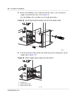
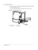
Installing the Breaker Interface Panel for the Ethernet Routing Switch 8010co Chassis
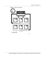
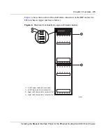
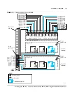
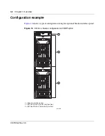
Figure 10
Power and grounding example
3 2
PS (+)
Lower Shelf
PS (+)
Upper Shelf
PS (-)
Lower Shelf
PS (-)
Upper Shelf
A/B Input Feed
Returns
– 48 VDC
A/B Input Feeds
1 3 2 1
3 2 1 3 2 1
A
2
A
1
B
1
B
2
Power terminal block (BIP)
Return Secondary B
Return Primary B
Return Secondary A
Return Primary A
Gnd PS 1 upper
-DC PS1 Upper
-DC PS2 Upper
-DC PS3 Upper
-DC PS1 Lower
-DC PS2 Lower
-DC PS3 Lower
+DC PS1 Upper
+DC PS2 Upper
+DC PS3 Upper
+DC PS1 Lower
+DC PS2 Lower
+DC PS3 Lower
Gnd PS 2 upper
Gnd PS 3 upper
PS 1
+ DC
– DC
PS 1
+ DC
– DC
PS 2
+ DC
– DC
PS 3
PS 3
+ DC
– DC
PS 1
+ DC
– DC
PS 1
+ DC
– DC
PS 2
+ DC
– DC
PS 3
+ DC
– DC
DC
Gnd PS 1 lower
Gnd PS 2 lower
Gnd PS 3 lower
Gnd BIP
Gnd upper shelf
Gnd lower shelf
Upper shelf
Lower shelf
= Chassis ground
= Earth ground
Chassis
ground stud
Chassis
ground stud
-48 VDC Primary A
-48 VDC Secondary A
-48 VDC Primary B
-48 VDC Secondary B
10760EB
Cable not
supplied
Cable not
supplied
Rack
grounding strip
example
Equipment
rack
PS 3
+ DC
– DC
Legend:
= Redundant equipment
Содержание 8010co
Страница 6: ...6 312755 G Rev 00...
Страница 10: ...10 Contents 312755 G Rev 00...
Страница 14: ...14 Tables 312755 G Rev 00...
Страница 18: ...18 Preface 312755 G Rev 00...
Страница 66: ...66 Chapter 2 Installation 312755 G Rev 00...