


19
Installing the Breaker Interface Panel for the Ethernet Routing Switch 8010co Chassis
Chapter 1
Overview
This chapter provides an overview of the BIP and covers the following topics:
•
Physical description
•
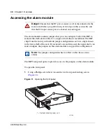
“Accessing the alarm module” on page 30
•
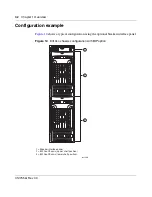
“Configuration example” on page 32
Physical description
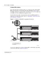
The BIP provides a central rack location where redundant input DC power feeds
are connected and routed to one or two 8010co chassis. The BIP also provides an
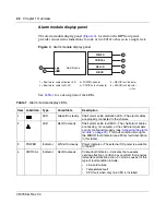
alarm module and display panel that monitors system components, generates
alarms, and controls LED status indicators (requires 8010co chassis configured
with an 8691SF or 8691omSF CPU Module). The alarm module provides total
system status to the central office.
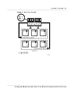
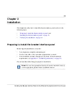
Figure 1
shows the breaker interface panel. Descriptions of the front panel
components follow the figure.
Figure 1
Breaker interface panel
POWE
R
CRITIC
AL
MAJO
R
MINO
R
10370FB
Содержание 8010co
Страница 6: ...6 312755 G Rev 00...
Страница 10: ...10 Contents 312755 G Rev 00...
Страница 14: ...14 Tables 312755 G Rev 00...
Страница 18: ...18 Preface 312755 G Rev 00...
Страница 66: ...66 Chapter 2 Installation 312755 G Rev 00...