Basic Configuration and Setup
Setting up LAN Emulation
Centillion 1200N ATM Switch User Manual
8-11
NTP 297-8103-903
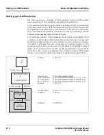
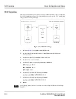
Use the following steps to set up shaded area of the diagram. All data in this section,
including addresses, are examples:
1.
Connect cables as in the diagram above and power on all the equipment.
2.
Adjust the clock mode of the switch (#2) to SLAVE. The LES is set to provide
a MASTER clock.
3.
Check the switch’s local information.
DISPLAY network
4.
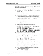
Set the line interface card parameters, ILMI parameters and ATM signaling
parameters. (For both PNNI interface port 00 and UNI interface port 03.)
If connections such as an ILMI signaling or PNNI exist for that port, those
must be deleted before line interface parameters can be changed.
DEL signaling 00 0
DEL ilmi 00 0
DEL signaling 03 0
DEL ilmi 03 0
5.
Set the line interface parameters for PNNI interface port 00.
SET interface 00
Interface (pri_uni|0 pri_nni|1 pub_uni|2)? 1
Forum/ITU (forum|0 itu|1)? 0
IDLE Cell (unassigned|0 idle|1)? 0
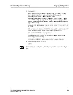
Valid VPI (0-8[bit])? 6 (based on interface type)
Valid VCI (0-8[bit])? 8 (based on interface type)
Line Interface 00 has been registered.
6.
Set the line interface parameters for UNI interface port 03.
SET interface 03
Interface (pri_uni|0 pri_nni|1 pub_uni|2)? 0
Forum/ITU (forum|0 itu|1)? 0
IDLE Cell (unassigned|0 idle|1)? 0
Valid VPI (0-8[bit])? 0
Valid VCI (0-8[bit])? 10
Line Interface 03 has been registered.
If a line interface port is connected to an ATM-NIC, verify that the Valid VPI
and Valid VCI values are 0 and 10 respectively. The ATM-NIC in this example
only supports VPI=0 and VCI up to 1023.
If the NIC attached to the line interface port carries Management Information
Base (MIB) information, ILMI can automatically obtain these valid VPI and
VCI parameters, otherwise they must be set manually.
7.
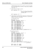
For UNI interface port 03 connected to the ATM-NIC, set ILMI timing
parameters. ILMI uses VPI/VCI=0/16.
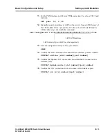
SET ilmi 03 0 16 5 60 20

