6
4
Ultrasonic Sensor Installation
4.1
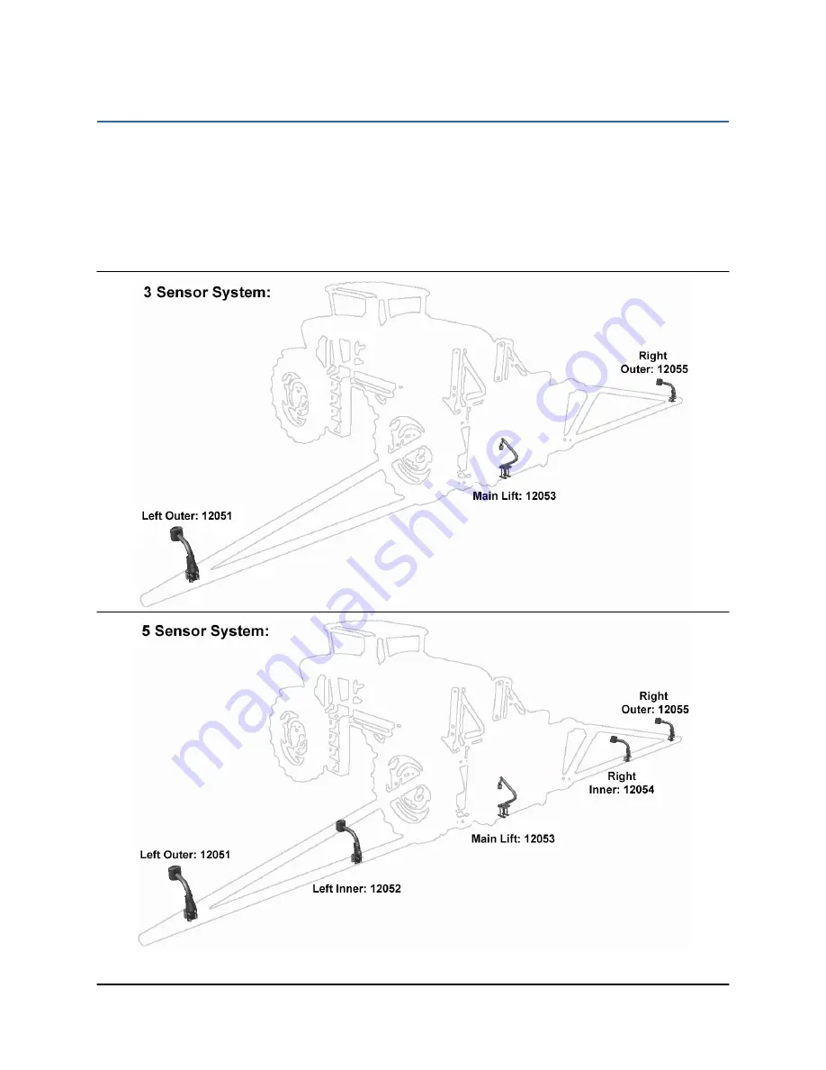
Ultrasonic Sensor Serial Number Arrangement
When installing the UC5 sensors, start with the smallest serial number on the left-hand side,
and proceed to the largest serial number on the right hand side. Each UC5 sensor has a serial
number stamped on the sensor housing.
Apply a light coating of the supplied Permatex Anti-seize grease to all threaded
parts upon installation.
Figure 4: Sensor Serial Number Arrangement
Содержание UC5 Rogator 600
Страница 1: ...Spray Height Controller Rogator 600 Installation Manual RG09 ...
Страница 6: ...3 3 Kit Parts 3 1 Kit Overview Figure 2 RG09 System Parts ...
Страница 7: ...4 3 2 Hydraulic Plumbing Figure 3 RG09 Hydraulic Plumbing ...
Страница 11: ...8 Figure 7 Wing Sensor Bracket Mounting on Chafer Boom Outer Inner ...
Страница 19: ...16 Figure 19 Input Module Mounting ...
Страница 27: ...24 10 3 ITEM C03 43210 03 CABLE UC5 NETWORK 18 AWG 3M 10 4 ITEM C04 43210 01 CABLE UC5 NETWORK 18 AWG 1M ...
Страница 28: ...25 10 5 ITEM C05 43210 10 CABLE UC5 NETWORK 18 AWG 10M 10 6 ITEM C10 43230 04 CABLE UC5 VALVE DT TO DT ...
Страница 29: ...26 10 7 ITEM C20 43240 01 CABLE UC5 INTERFACE TILT DT ...
Страница 30: ...27 10 8 ITEM C21 43240 31 CABLE UC5 INTERFACE MAIN DT WITH AUX 1 2 3 ...


