background image


1-

a )


Before


installing


About


e n v ironment


for


installation


?

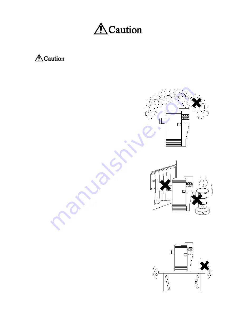
   Do not install in  humid and dusty room.  It may   


 cause fire and/or electric shock.   


?

   Do not install the equipments near the   


  heat emitting apparatus such as stove   


  and heater or near the flammables such   


  as curtain. It may cause fire.   


?

   Do not place on shaky table or inclined   


  location. It may fall or drop and cause 


  injury to nearby persons.   


Содержание PR53FS

Страница 1: ...DIRECT CARD PRINTER PR53FS LE Operation Manual Ver 1 0 Sep 05...

Страница 2: ...e parts Section 3 Installation a Environment for installation b Space for installation c Preparation for installation d Connecting the Printer to Computer e Power ON f Settings after the Power ON Sect...

Страница 3: ...Section 7 Periodical replacement of parts a Replacing Input Roller b Replacing Print Head c Replacing fan filter Section 8 Basic specification Section 9 Configuration of the equipment Section 10 Troub...

Страница 4: ...of death or serious injury This indicates that there is possibility of death or serious injury This indicates that there is a possible cause of injury and or damages on properties This manual MUST be...

Страница 5: ...oom It may cause fire and or electric shock Do not install the equipments near the heat emitting apparatus such as stove and heater or near the flammables such as curtain It may cause fire Do not plac...

Страница 6: ...e ventilation opening is closed by obstacle heat can not be dissipated and it may cause a fire Place with the clearance as shown in the illustration Do not place in the room with much vibration It may...

Страница 7: ...used without removing a small amount of electricity runs continuously through the dust by the effect of moisture etc and may eventually cause a fire Be careful so that the power supply cord is not da...

Страница 8: ...connected to an copper rod which is buried in the ground at the depth of 65cm 26inch or deeper Grounding line may not be connected to the following points Gas pipe There is a danger of fire and or exp...

Страница 9: ...lectric shock If by any chance metal pieces or water get inside the equipment turn off the main switch and plug off the power supply cord from the outlet Then contact the dealer from whom you have pur...

Страница 10: ...from whom the equipment was purchased In case of thunder for the purpose of safety turn OFF the main switch and plug off the power cord This will prevent burning of the equipment fire or electric sho...

Страница 11: ...t may cause card jamming or malfunction of the equipment Do not touch any part inside the equipment other than directed by this manual Read this manual carefully before performing recovering operation...

Страница 12: ...oken and cause fire or electric shock 1 e Other If the equipment is installed and operated at near TV set or radio it may cause an interference such as noise or flicker In such case use the outlet con...

Страница 13: ...Section 2 Preparation 2 a Package contents Following items are packed in the carton together with the printer If anything is missing contact the dealer from whom you have purchased...

Страница 14: ...possible with one roll of ink ribbon Ink ribbon has been changed in the middle There has been errors in the middle Head lifting has been done in the middle Abnormal operation which is not allowed in t...

Страница 15: ...t pins with fingers Static may damage the circuits inside this part At the printing edge of the Print Head is very high compound of heating element So never touch this part with a hard object fingers...

Страница 16: ...e item Replacing Input Roller at 7 a For cleaning the Rollers refer the item Cleaning the rollers at 6 a Fan Filter Recommended Replacement period every 6 months Do not wash with water It may cause eq...

Страница 17: ...f the parts Front side of the printer 1 Front Access Cover 2 Top Cover 3 Rear Cover 4 Operation Panel 5 Card Feeding Unit 6 Power Switch 7 Reject Card Exit 8 Front Cover 9 Card Stacker Rear side of th...

Страница 18: ...1 Circuit Protector 2 USB Connector 3 Power Cord Receptacle...

Страница 19: ...Front Access Panel 1 Input Roller Module 2 Ribbon Cartridge Holding Lever 3 Manual Rotation Knob 4 Ribbon Cartridge...

Страница 20: ...MEMO...

Страница 21: ...agnetic field It may destruct the magnetic encoding data if the Magnetic Encoder is being used In the worst case it may cause equipment trouble 3 b Space for installation The space for the operation a...

Страница 22: ...rely connected for this printer The maximum power consumption of this printer is 120W Avoid power failure or voltage drop as much as possible When the power is turned OFF wait for at least 3 sec befor...

Страница 23: ...e communicating Error LED Red Indicates Error This alarms that the printer is in error Power LED Green Power ON indicator This shows the power is ON Ribbon Change Menu Key Normal User Use this key whe...

Страница 24: ...lease refer to Paragraph 10 Countermeasure for Trouble After releasing the error press Clear key to resume to Ready to Print If Cannot Recover Please Reset appears on the LCD resolve the trouble and p...

Страница 25: ...mode This function is invalid regardless of the setting in the user mode if the system is designed so that the data is not stored in the printer memory to prevent double printing Stopping the continu...

Страница 26: ...to move to the User Menu Then the first menu Card Count is displayed Basic Operation in the User Mode As the User Menu has the following layer structure select the desired item with the MENU key and...

Страница 27: ...pressing EXE key and decreases by CLEAR key Standard value is 0 Example of color adjustment The color image to be printed on the card consists of the 3 colors Cyan C Magenta M and Yellow Y These color...

Страница 28: ...am has two parts one is the Base Program which controls the basic communications and the other is the Main Program to control all functions In addition to those two it is possible to check and confirm...

Страница 29: ...EXE Return to Parent Mode EXE Image Data Print EXE Print Return to normal Mode EXE Return to Parent Mode EXE Ready to Print Removable Ribbon User Mode CLR B ack EXE Go User Mode Push Menu Key Card Cou...

Страница 30: ...ent Mode EXE Printer Status CLR EXE submenu u Printer Status Push MENU Key Base Program EXE Key Print Print Retry Main Program Head Number Serial Number ROM Version EXE sub menu OFF OFF Remove Normal...

Страница 31: ...ecome even 4 Place the card weight on top of the card and close the cover Hold the card s by the edge When loading the cards with mag stripe be careful to the direction of the card Regarding the direc...

Страница 32: ...hen loading the cards stack the cards evenly as marked with in the figure below If it is stacked unevenly as shown with the mark in the figure below it may cause Pick Up Error or the stack may collaps...

Страница 33: ...Top Cover and take out the Ribbon Cartridge without lifting the Print Head by pressing RIBBON CHANGE key Normal print quality of the next printing will not be obtained Do not leave the ink ribbon cart...

Страница 34: ...up side of the cartridge to use as take up bobbin Set new ribbon onto the supply side of the cartridge Peel off the leading tape at the beginning of new ribbon and put it onto the empty bobbin Attach...

Страница 35: ...g operation leave the machine for about 5 min before restarting Correct printing may not be obtained if printed before the alcohol is completely dried Do not touch the rollers with hand Fingerprint ma...

Страница 36: ...alling After wiping off wait till it becomes completely dry before inserting it again 6 b Cleaning of the card transport rollers in Flip Turn Block Before beginning this operation please read the gene...

Страница 37: ...lean the whole surface of all 4 pairs of rubber rollers shown with and white mold rollers To clean them easily use the green handle located on front access area as shown in figure on right This handle...

Страница 38: ...is operation please read the general advice which appears in the beginning part of this section Wet and squeeze the soft cloth with alcohol for OA equipments and wipe the all surface of the roller in...

Страница 39: ...tion It may cause a trouble and or to have electrical shock Do not use solvents other than alcohol for cleaning OA equipments Using the solvent other than alcohol may damage the parts and may cause tr...

Страница 40: ...m card hopper 5 Push EXE key Set CleaningCard Put the cleaning card on card hopper Watch the position of the card put See the figure under part of this sheet 6 Push EXE key PleaseWait Now Cleaning Cle...

Страница 41: ...MEMO...

Страница 42: ...40000 frames N A Print Head Every 20000 frames Loader Application Fan Filter Every 6 months Philips Screw Driver Number of the printed frames is displayed on the LCD panel 7 a Replacing Input Roller...

Страница 43: ...touch there To replace a print head The figures on next page showing a print head fixed showing a print head removed To take the print head off Release the lever as pointed with C in fig Then hold th...

Страница 44: ......

Страница 45: ...lter Turn OFF the power without fail before the cleaning operation It may cause a trouble and or to have electrical shock A figure on right shows a part of back side of the right cover located just be...

Страница 46: ...or each of colors R G and B Output 256 grayscale control for each of colors Y M and C 5 Printing Size Max 85 5mm card longitudinal direction x 54 5mm card transverse direction 6 Printing Speed 30 seco...

Страница 47: ...witch the card path to printing unit eject unit or to reject unit Printing Unit The card moves through this unit five times to be printed 3 colors black color and protective overlay coating Print Head...

Страница 48: ...r priority Cover Open in this case is displayed on the LCD panel Close the cover and press Clear key Then the display changes to Card Empty Load the cards and press Clear key to return to Ready to Pri...

Страница 49: ...of range Make sure of ambient temperature is in the range of what is mentioned in Section 3 P 1 8 The process of printing data will be finished as error by some kind of reason Reissue the card Messag...

Страница 50: ...Ink ribbon is not set correctly Check whether the ink ribbon is correctly set in the cartridge Ribbon transport roller is dirty Clean the roller Improper card is used If a card which is already printe...

Страница 51: ...matically to the Card Eject Exit by pressing Clear key on the operation panel If the card can not be ejected in this method remove the jammed card manually The location Block of card jam is shown on t...

Страница 52: ...Block Layout...

Страница 53: ...d cards by the dealer P 35 A card is stuck in the Flip Turn Block First turn OFF the power Open the top cover and remove the card If necessary rotate the green handle and or green disk to transport in...

Страница 54: ...is damaged Replace with the new head The damage of the print head is caused by biting a solid particle between the head and the card while printing To avoid this do not use a dirty card or leave the r...

Страница 55: ...o press Ribbon Change key before taking out The message Ribbon Type incorrect is shown on the LCD display This does not mean the machine trouble but means incorrect operation P 20 Un supposed Dark are...

Страница 56: ...Ref Power does not turn ON Data can not be transmitted to the printer Check the connection of the power cord If the circuit protector lever above the power cord receptacle on the backside of the prin...

Страница 57: ...MEMO...

Отзывы: