54 - FORM NO. 56043097 / Adgressor
™
/ BR 850S, 850CS, 950S, 950CS, 1050S, 1050CS
ELECTRICAL SYSTEM
F
G
CURTIS CONTROLLER DIAGNOSTICS
Diagnostics Method A: Uses the machine’s control panel hourmeter display and wand switch indicator.
FUNCTION OF THE SPEED CONTROLLER STATUS LIGHT AND DISPLAY
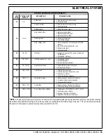
The Curtis 1237 speed control will output a fault code if there is a problem associated with the speed control and wheel drive system. See Figure
6. If a speed control fault occurs, the Hourmeter/Status display (F) will indicate “E 03”. When the E03 is being displayed and detects a fault the
Green Indicator (G) normally the accessory wand indicator light will fl ash a special error code sequence until the fault is corrected. See “Table 1”
for a description of the fault indications. Service Note: Instructions on how to read the error code status light. Example, OO O = two light fl ashes,
a short pause, one light fl ash, a long pause and the code will be repeated. This indicates a fault code 2,1.
Diagnostics Method B: Uses the optional handheld Curtis programmer.
PROGRAMMER DIAGNOSTICS
With a programmer, diagnostics and troubleshooting is more direct than with the LED alone. The programmer presents complete diagnostic
information in plain language, no codes to decipher. Faults are displayed in the Diagnostic Menu, and the status of the controller inputs/outputs is
displayed in the Test Menu.
The following 4-step process is generally used for diagnosing and troubleshooting an inoperative vehicle: (1) visually inspect the vehicle for obvious
problems; (2) diagnose the problem, using the programmer; (3) test the circuitry with the programmer: and (4) correct the problem. Repeat the last
three steps as necessary until the vehicle is operational.
Example: A vehicle that does not operate in “forward” is brought in for repair.
1
Examine the vehicle and its wiring for any obvious problems, such as broken wires or loose connections.
2
Connect the programmer, put it in diagnostic mode, and read the displayed fault information. In this example, the display shows “No Faults Present”, indicating
that the controller has not detected anything out of the norm.
3
Put the programmer in test mode, and observe the status of inputs and outputs in the forward direction. In this example, the display shows that the forward
input did not activate when “forward” was selected, which means the problem is either in the electronic throttle or the throttle wiring.
4
Check or replace the electronic throttle and wiring and repeat the test. If the programmer shows the forward switch closing and the vehicle now drives normally,
the problem has been corrected.
Refer to the Status Fault Codes (Table 1) for suggestions covering a wide range of possible faults.
DIAGNOSTIC HISTORY
The handheld programmer can be used to access the controller’s diagnostic history fi le. Connect the programmer, press the MORE INFO key, and
then while continuing to hold the MORE INFO key, press the DIAGNOSTICS key. The programmer will read out all the faults that the controller has
experienced since the last time the diagnostic history fi le was cleared. The faults may be intermittent faults, faults caused by loose wires, or faults
caused by operator errors. Faults such as HPD or over temperature may be caused by operator habits or by overloading.
After a problem has been diagnosed and corrected, clearing the diagnostic history fi le is advisable. This allows the controller to accumulate a new
fi le of faults. By checking the new diagnostic history fi le at a later date, you can readily determine whether the problem was indeed completely
fi xed.
To clear the diagnostic history fi le, go to the Special Program Menu (by pressing and holding the MORE INFO key, and then pressing the PROGRAM
key), scroll through the menu until “Clear Diagnostic History” is the top line in the display, and then press MORE INFO again. The programmer will
prompt you to acknowledge or cancel.
See the CURTIS PROGRAMMER MANUAL 56043101 for more detail on programmer operation.
FIGURE 6
Содержание Adgressor BR 1050CS
Страница 74: ...72 FORM NO 56043097 Adgressor BR 850S 850CS 950S 950CS 1050S 1050CS ELECTRICAL SYSTEM Drive Motor Breakdown ...
Страница 81: ......
Страница 82: ...www nilfisk advance com 2006 ...

