


038
www.ruggedaq.com
DATALOGGER
NI400
NI400
039
www.ruggedaq.com
DATALOGGER
NI400
NI400
The 32-bit tool is able to works under 64-bit operative system but is not able to create the
connection because the driver of dial-up connection is different.
Also in this case, to solve this problem you have to uninstall the tool (Control Panel / Pro-
grams and Features) and re-install the correct version of the NI400 Connection Tool.
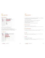
HOW to disconnect PC from the NI400
To disconnect the PC from the NI400 follows this steps:
on the NI400 web page press
Logout
button;
on Microsoft Windows select the
Network icon
on the application bar;
Networks menu
will open;
Press on
Disconnect
button to close the Dial-Up connection between PC and the NI400
NOTE: when the USB cable is unplugged the NI400 is rebooted. This is necessary to
switch from the USB power supply to the NI400 power supply (internal batteries or
external power supply)
Unplug USB cable without any disconnection procedure
If you unplug the USB cable without following the correct disconnection procedure the
NI400 is rebooted. Under “Data Monitor – Events” a “Power Fail” log appears.
USB connection by USB Isolator-Cable
USB port in the NI400 is not isolated.
For the connection between PC and the NI400, it is recommended to use an isolated USB
cable.
The USB isolator cable effects a potential decoupling of all USB connections. It is the pro-
fessional tool to avoid and fight ground loops and equalize currents. It is also important to
protect the system against overvoltage, that could damage NI400 or cause flood readings.
USB isolated cable is especially recommended when the PC and the NI400 are connected
to the main electricity network.
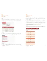
If you are using this cable, you need to consider that the maximum supplied current is
400mA, compared to a USB port that provides 500mA (maximal 400mA sourced from the
500mA primary input).
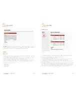
Therefore, when the NI400 is powered using an isolated USB cable it should be noted
that:
§
the USB port of the PC must be capable of delivering at least 500mA current;
§
the connected sensor must not draw more than 35mA.
If these two conditions are not respected, you may experience some communication and
power supply disconnections.
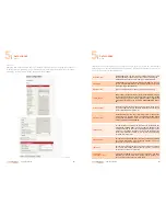
Figure 36
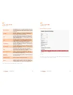
Figure 37
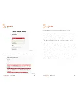
Figure 38
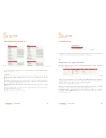
Figure 39
3
3