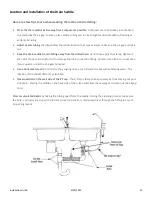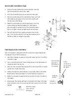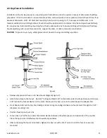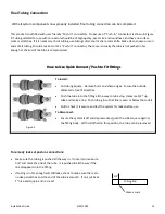
Installation Guide
6/29/2023
6
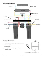
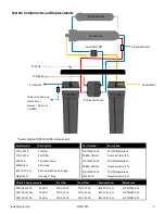
Storage Tank Assembly and Prep
1.
Apply 3
-
4 wraps of Teflon® tape to the tank threads and thread tank valve on to the tank. DO NOT OVER
TIGHTEN!
2.
Connect
3/8”
white tubing from tee connected to inlet port (on back) of the post filter housing
3.
Using a low pressure bicycle tire gauge, check that the empty tank precharge is 7
-
8 psi. Adjust accordingly if
needed.
Install the Membrane and Flow Restrictor
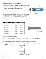
The membrane and flow restrictor are packed in the box and must be installed.
1.
Disconnect the feed supply tubing attached to the cap of the membrane
housing and then unscrew the cap from the housing.
2.
Insert the membrane, o
-
ring end first with the brine seal on the cap
end. Push it in all the way.
3.
Replace the housing cap and reconnect the feed supply tubing
Each membrane output size has to have an appropriate flow restrictor for the
system to operate properly. If not already in place, the inline flow restrictor
installs on the red brine tube coming from the bottom of the membrane
housing as shown in the diagram to the right. Make sure the arrow points away
from the membrane.
Brine Seal
O
-
ring end
Cap
Membrane
Flow restrictor
Tank
System SKU
25 GPD
220 ml/min
3.2
PRO
-
41110
-
A
25 GPD
220 ml/min
4.5
PRO
-
41120
-
A
50 GPD
420 ml/min
3.2
PRO
-
41310
-
A
4.5
50 GPD
420 ml/min
PRO
-
41320
-
A
3.2
75 GPD
650 ml/min
PRO
-
41410
-
A
4.5
75 GPD
650 ml/min
PRO
-
41420
-
A
3/8”
Tank Valve
Air Valve
Содержание PRO-41000-A Series
Страница 20: ...Installation Guide 6 29 2023 20...


