background image

NEC Versa

®

 LX Notebook Computer

V

ERSA 

LX

S   E   R   V   I   C   E      A   N   D      R   E   F   E   R   E   N   C   E

M   A   N   U   A   L

Содержание Versa LX

Страница 1: ...NEC Versa LX Notebook Computer VERSA LX S E R V I C E A N D R E F E R E N C E M A N U A L...

Страница 2: ...of the Warranty Statement accompanying each product However actual performance of each such product is dependent upon factors such as system configuration customer data and operator control Since impl...

Страница 3: ...Bridge Battery 1 13 ChipSet 1 14 Chapter 2 System Configuration and Setup Power Sources for Your NEC Versa 2 2 Using the AC Adapter 2 2 Powering On 2 4 Using the Main Battery Pack 2 4 Determining Batt...

Страница 4: ...27 Launching the Application and Driver CD 2 27 Installing the Software 2 28 Partition Magic 2 28 Using Partition Magic 2 28 Intel LANDesk Client Manager 2 29 SystemSoft PowerProfiler 2 30 SystemSoft...

Страница 5: ...e Assembly LCD Panel Latch Switch Assembly 3 23 VersaGlide Assembly 3 23 LCD Panel Switch Board 3 23 LCD Panel Assembly 3 24 LED Sub Assembly 3 25 Hard Drive and PC Card Assemblies CMOS Battery Buzzer...

Страница 6: ...ubleshooting 7 2 Helpful Questions 7 4 Chapter 8 Getting Services and Support Services and Support Contact Information 8 2 NEC CSD Web Site 8 2 NEC CSD FTP Site 8 3 Email Fax to Support Services 8 3 N...

Страница 7: ...eassembly provides detailed instructions on how to disassembly the notebook Chapter 4 System Board Layout shows the system boards and the board connectors Chapter 5 Illustrated Parts Breakdown shows t...

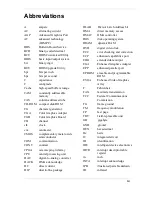
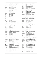
Страница 8: ...AC digital to analog converter DACK DMA acknowledge DC direct current DIP dual in line package DLAB Divisor Latch Address bit DMA direct memory access DMAC DMA controller DOS disk operating system DRA...

Страница 9: ...Peripheral Component Interconnect PDA personal digital assistant PFP plastic flat package PIO parallel input output pixel picture element PLCC plastic leaded chip carrier PLL phase lock loop p p peak...

Страница 10: ...xi VESA video electronics standards association VFC VESA compliant feature connector VGA Video Graphics Array VRAM video RAM W watt W write XGA Extended Graphics Array...

Страница 11: ...Getting to Know the NEC Versa LX Around the Front of the System Around the Back of the System Around the Left Side of the System Around the Right Side of the System Around the Bottom of the System In...

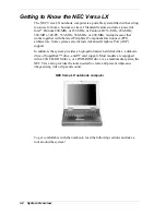
Страница 12: ...pheral Component Interconnect PCI architecture Some systems also include Advanced Graphics Port AGP support In addition the system provides a high performance hard disk drive a diskette drive or Super...

Страница 13: ...hics Array SVGA panel 13 3 inch color Thin Film Transistor TFT Extended Graphics Array XGA panel 14 1 inch Thin Film Transistor TFT Extended Graphics Array XGA panel To adjust the LCD panel brightness...

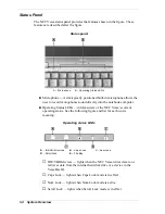
Страница 14: ...omputer Operating Status LEDs informs users of the NEC Versa s current operating status See the following figure and list for each icon s meaning Operating status LEDs A IDE VBIII Devices B Caps Lock...

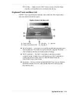
Страница 15: ...EDS E VersaBay III Stereo Speakers provide stereo sound for multimedia presentations or listening pleasure The built in sound system also supports 3D sound which simulates the latest surround sound te...

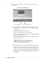
Страница 16: ...indicate that battery power is at 8 capacity or less Lights amber blinks when in Suspend mode to indicate that battery power is at 3 capacity Note When both the primary and a secondary battery are ins...

Страница 17: ...tor Port F Parallel Port G PS 2 Port PortBar Notches Use these notches to secure the PortBar to the back of the system Serial Port Use this port to connect an external modem or other serial device Exp...

Страница 18: ...both a mouse and a keyboard at the same time Around the Left Side of the System The left side of the NEC Versa offers the following features which are described after the figure Left side features A F...

Страница 19: ...rt Uses a television set equipped with an S Video input jack as an external monitor This port supports both NTSC and PAL signals TV Out RCA Port Uses a television set equipped with a standard RCA jack...

Страница 20: ...ging in headphones disables the built in system speakers Line In Uses another audio system like a home stereo as an input source Use a cable to connect to the Line Out port on the other audio system t...

Страница 21: ...off until he she slides forward the Power Sleep button again to bring it out of Suspend mode In addition the Smart Power switch invokes an orderly shutdown in the Windows 95 and Windows NT environmen...

Страница 22: ...tery Bay Release Latch Allows the user to release and remove the system s main battery NEC VersaBay III Release Lock and Latch Allows the user to remove the device currently installed in the bay Batte...

Страница 23: ...provides the NEC Versa system with its audio I O capabilities via a line in jack headphone and microphone jacks It is situated on top of the main board CMOS Battery The lithium battery 3 Volts 30 mAH...

Страница 24: ...3 366 400 MHz CPU 320 pin TCP 82430TX supporting Tillamook 82443BX supporting Pentium PIIX4E all models Intel System Controller PC97338VJG National Semiconductor Super I O 100 pin TQFP ATI 3D Rage LT...

Страница 25: ...2 System Configuration and Setup Power Sources for Your NEC Versa BIOS Setup NEC CSD Utilities Software Applications and Drivers...

Страница 26: ...power sources Using the AC Adapter Use the AC adapter and power cable that came with your NEC Versa to run your computer on alternating current AC power or to recharge the battery pack Use the AC ada...

Страница 27: ...dapter as follows 1 Connect the AC adapter cable to the power port on the back of your NEC Versa 2 Plug one end of the AC power cable into the AC adapter and the other end into a properly grounded 120...

Страница 28: ...Soft s PowerProfiler for Window NT systems only described later in this chapter Both provide important battery status information When battery power is very low the power LED flashes amber When batter...

Страница 29: ...alled in the battery bay Read the precautions printed on the battery later in this chapter Determining Battery Status You can determine battery status via the battery gauge LEDs on the front of the Li...

Страница 30: ...ry gauge LEDs use SystemSoft s PowerProfiler to determine battery status Click on the battery icon located on the taskbar The PowerProfiler battery page displays To return the battery to its normal st...

Страница 31: ...th a dry cloth when they get dirty Keep the battery out of the reach of children Replacing the Battery Replace the battery pack installed in your NEC Versa system as follows Note Use the batteries in...

Страница 32: ...tery 5 Insert the new battery as follows Locate the alignment groove on the edge of the battery Locate the alignment groove inside the battery bay Align the grooves on the battery with the grooves in...

Страница 33: ...over 140 F 60 C may cause damage Do not drop or impact the battery Do not disassemble the battery Do not solder the battery Do not puncture the battery Do not use a battery that appears damaged or def...

Страница 34: ...F8 and Fn F9 function keys to control the brightness NEC VersaBay III Battery The NEC VersaBay III battery provides an optional second Lithium Ion Li Ion battery to use in your NEC Versa LX computer...

Страница 35: ...protect your system from unauthorized use Use BIOS setup to set the current time and date customize your operating system to reflect your computer hardware secure your system with a password balance...

Страница 36: ...imilar to the following BIOS Setup Main Menu Use the up and down arrow keys located on the lower right corner of the keyboard to toggle through the BIOS Setup menu items How to Use BIOS Setup The foll...

Страница 37: ...grayed out are not available for the current selection Using Keys The following table lists the BIOS Setup keys and their functions BIOS Setup Key Functions Key Function Moves the cursor between the...

Страница 38: ...Not installed 1 2 MB 5 25 1 44 MB 3 5inch Internal Auto User Defined CDROM SuperDsk Not installed 32 Bit Mode On Off VersaBay Auto CDROM User Defined CDROM SuperDsk Not installed 32 Bit Mode On Off D...

Страница 39: ...sabled Enabled Suspend Option Suspend STF Auto Save to File Enabled Disabled Panel Brightness Auto User Defined Suspend Warning Tone Enabled Disabled Remote Power On 8 Enabled Disabled Resume Signal 8...

Страница 40: ...hese setup items are only visible when system is docked 2 Supervisor password has to be previously set up 3 Only active after a password is set up 4 Available when power savings is set to custom 5 Res...

Страница 41: ...ctor Virus Protection Write protects the boot sector of the hard disk drive to avoid infection by some virus types Advanced CMOS Setup Advanced CMOS settings let you define the following functions Vid...

Страница 42: ...AC power is connected to your NEC Versa system power management is usually disabled If you enable this parameter the system automatically activates the power management profile you set even when AC po...

Страница 43: ...ingly The save to file area is present on your hard drive pressing the Fn Power Sleep key combination puts the system into Save to File mode Before using the Power Sleep button to put the system into...

Страница 44: ...IDE devices as bootable devices Peripheral Setup The Peripheral Setup menu displays the connection locations between the system and the Input Output I O ports This menu also lets you specify different...

Страница 45: ...enter BIOS Setup access the system at startup or resume from Suspend depending on your configuration selection Your system is not protected until you set a user password and you are not prompted to e...

Страница 46: ...e your NEC Versa s STF feature follow these steps 1 Access the BIOS setup utility 2 Select Power Management from the Setup Main Menu 3 Move the cursor down and highlight Suspend Option 4 Press the PgU...

Страница 47: ...e local office in your country Only use the BIOS upgrade diskette for your specific model and be sure to prepare the diskette before upgrading the BIOS Preparing the BIOS Upgrade Diskette Before using...

Страница 48: ...y Plug in your AC cable before restarting the flash utility 3 Press Enter to continue The utility checks the currently installed BIOS version and the diskette s BIOS version The Main menu appears 4 Us...

Страница 49: ...es IR setup utility to enable the IR port Windows 95 only enables the IR port NEC supplied mouse driver Windows NT only use this option to take advantages of the VersaGlide features The NEC Customize...

Страница 50: ...ows 9x press F8 3 From the Startup menu select Safe Mode Command Prompt Only usually Option 6 4 Enter MS DOS At the c prompt type cd necutils hdprep and press Enter to change to the necutils hdprep di...

Страница 51: ...e software applications available on the Application and Driver CD vary according to your operating system environment and may include PowerQuest PartitionMagic Intel LANDesk Client Manager SystemSoft...

Страница 52: ...Driver CD dialog box appears follow these steps to install the desired software 1 Click the selection tab of your choice 2 Select the desired application 3 Click the Installation selection to activat...

Страница 53: ...ts include network interface cards memory modules printers and software applications LANDesk Client Manager uses the Desktop Management Interface DMI standard established by the Desktop Management Tas...

Страница 54: ...ted plug and play capability by automatically diagnosing and resolving many PC card problems When you insert a new PC card into a PC card slot the Wizard displays a representation of the slot with inf...

Страница 55: ...integrated set of tools provides services ranging from basic email to exciting conferencing broadcasting and web authoring capabilities Netscape Navigator Netscape Navigator is a popular software for...

Страница 56: ...y window Windows NT Systems In Windows NT enable the IR port using the hardware BIOS setup utility Follow these steps to enable the IR port 1 Access the BIOS Setup utility at power on Just press F2 wh...

Страница 57: ...3 Disassembly and Reassembly Required Tools and Equipment Disassembly Reassembly...

Страница 58: ...sembly procedures Some earlier units did not have a user removable hard drive Follow the instructions carefully to properly disassemble the systems When disassembling the system unit follow these gene...

Страница 59: ...ide the battery release latch toward the back of the system and hold firmly Battery Release Latch A Battery Bay Release Latch 2 Continue to hold the battery release latch as you slide the battery out...

Страница 60: ...rsaBay III 1 Locate the VersaBay III release lock and release latch on the bottom of the unit VersaBay III release lock A VersaBay Release Lock B VersaBay Release Latch 2 Slide the lock to the unlocke...

Страница 61: ...f the latch Releasing the device Keyboard Memory Module Switch Settings Use the following steps to access remove keyboard memory and switch settings 1 Open the LCD panel 2 Locate the two keyboard reta...

Страница 62: ...Be careful not to twist the keyboard cable Remove the keyboard cable from the main board by pulling up on the inserts on both sides of the cable connector To remove an installed SO DIMM follow these...

Страница 63: ...key keyboard Switch 3 Reserved for factory use Default is OFF Switch 4 Reserved for factory use Default is OFF Default Switch Settings Non AGP Models Switch Settings for AGP Models The AGP system has...

Страница 64: ...Gently lift up the edge of the keyboard nearest the LCD and slide the keyboard toward the LCD screen to release the tabs that secure it CAUTION Never use a pencil to change switch settings Residue fro...

Страница 65: ...f you need to install replace SO DIMM modules do it while the system is already disassembled Disassembly Differences You must determine at this time if the system you are servicing has a user removabl...

Страница 66: ...of the system can identify a system with a user replaceable hard disk drive If the model number has the letter A in the next to last position of the number the unit has a user replaceable hard disk d...

Страница 67: ...4 Lift and disconnect the CPU assembly from the unit File Bay Assembly Remove the file bay assembly as described below 1 Remove one screw A from the bottom of the NEC Versa as shown in the following...

Страница 68: ...rd drive lever B and pull up the lever Be sure that both sides of the lever are raised Hard Disk Drive in the drive bay A Screw B Hard Disk Drive Lever C Hard Disk Drive 3 With the lever raised place...

Страница 69: ...t Cover The following describes the steps to remove the front cover 1 The file bay retaining screw B on the bottom of the system should have been removed in a prior step If not remove it now 2 Remove...

Страница 70: ...VersaGlide assembly or LCD panel latch switch assembly if necessary If these items do no need replacing skip the next section Speaker Assembly VersaGlide Assembly LCD Panel Latch Switch Assembly 1 Po...

Страница 71: ...connector CP17 B on the LCD panel latch switch board 2 Remove 2 screws A and lift from the front cover assembly A LCD Cover Panel Switch Board Screws B Connector CP17 This completes the disassembly o...

Страница 72: ...ws LED Sub Assembly The LED sub assembly consists of a board that contains three connectors and status LEDs The connectors are for the LCD panel switch main board and microphone A Connector CP13 B Con...

Страница 73: ...release the LED cable and anchor from the LCD panel assembly PC Card Assembly CMOS Battery Buzzer and Audio Board The PC card assembly CMOS battery buzzer and audio board may be removed and replaced...

Страница 74: ...t connector P1 A 2 Remove one screw B and lift and remove the port cover plate 3 Remove two screws C and disconnect the audio board D by gently lifting the front edge of the audio board and disconnect...

Страница 75: ...emblies Bridge Battery Power Switch 1 The bridge battery A is now accessible on the bottom assembly 2 To remove the Power switch simultaneous slide it to the front and gently lift the Power switch fro...

Страница 76: ...tilt feet on the bottom assembly All doors snap in and out To remove the tilt feet open the foot and slightly compress the four sections together and snap out Disassembly Non User Replaceable Drive S...

Страница 77: ...CPU Bay Cover Screws 2 Remove the CPU cover 3 Remove three screws A as shown in the following figure A Screws 4 Lift and disconnect the CPU assembly from the unit Front Cover The following describes...

Страница 78: ...sections of this chapter 4 Disconnect the VersaGlide cable from connector P11 and speaker assembly cable from connector P10 both located on the main board 5 Carefully separate and lift the front cove...

Страница 79: ...bly VersaGlide Assembly Remove the VersaGlide and cable assembly instructions as follows 1 Disconnect the LCD panel switch cable from connector CP16 A on the VersaGlide assembly 2 Remove the four scre...

Страница 80: ...ly of the front cover assembly Reverse this procedure to properly reassemble LCD Panel Assembly Remove the LCD Panel assembly as follows 1 Disconnect cables from the LCD cable at P4 on the main board...

Страница 81: ...ne 1 Disconnect the microphone cable at connector CP11 2 Remove the microphone and cable by gently pulling from the LCD assembly LED Board and LED Board Cable 1 Remove two screws and disconnect the ca...

Страница 82: ...rd drive assembly from the system A Hard Disk Drive Screws PC Card Assembly 1 Remove three screws A 2 Lift the PC card assembly from the right side of the system A CPU Assembly Screws CMOS Battery 1 D...

Страница 83: ...udio board and disconnecting from the main board 4 Lift the main board from the remainder of the system A Main Board Screws B Connector P1 C Audio Board D Port Cover Plate Screw Fan Assembly The fan a...

Страница 84: ...the Power switch slide it to the front while at the same time gently lifting the power switch from the bottom assembly 3 Remove the Bracket Insulator assemblies by removing three screws A and lifting...

Страница 85: ...Base Assembly There are doors and tilt feet on the bottom assembly All doors snap in and out To remove the tilt feet open the foot and slightly compress the four sections together and snap out Reassem...

Страница 86: ...4 System Board Layout Audio Board Connector Board LCD Panel Switch Board LED Status Board Main Board...

Страница 87: ...4 2 System Board Layout Audio Board A Connector P31 underside Connector Board A Connector CP10 B Connector CP9 C Connector CP8 D Connector CP7...

Страница 88: ...System Board Layout 4 3 LCD Panel Switch Board A Connector CP17 LED Status Board A Connector CP13 B Connector CP12 C Connector CP11 D Microphone...

Страница 89: ...4 4 System Board Layout Main Board A Connector P5 B Connector P4 C Connector P2 D Connector P1 E Connector P8 F Connector P9 G Connector P28 underside H Connector P29 underside I Connector P14...

Страница 90: ...5 Illustrated Parts Breakdown Illustrated Parts Breakdown Non AGP Models Parts List Non AGP Models Illustrated Parts Breakdown AGP Models Parts List AGP Models...

Страница 91: ...5 2 Illustrated Parts Breakdown Illustrated Parts Breakdown Non AGP Models...

Страница 92: ...Cap R 136 639512 002A 10 LCD Rubber Cushion 136 639309 001B 11 Screw Hole Cover 136 639310 001A 12 Audio Board 136 243483 001A includes items 23 24 13 Hard Drive Assembly 2GB 3GB 5GB 808 877280 304A...

Страница 93: ...20804 009A 34 Buzzer 802 870076 001A 35 Power Switch 136 639535 001A 36 I O Cap Assembly 136 243478 001A 37 Docking Station Cap Assembly 136 243479 001A 38 Fan 25 2510 5V 808 876290 002A 39 Microphone...

Страница 94: ...Illustrated Parts Breakdown 5 5 Illustrated Parts Breakdown AGP Models...

Страница 95: ...36 639512 002A 10 LCD Rubber Cushion 136 639309 001B 11 Screw Hole Cover 136 639310 001A 12 Audio Board 136 243483 002A 13 Hard Drive Assembly 3 GB 4 GB 6 GB 10 GB 050 01649 000 050 01651 000 050 0165...

Страница 96: ...Power Switch Button 136 639535 001A 36 I O Cap Assembly 136 243478 001A 37 Docking Station Cap Assembly 136 243479 001C 38 Fan 25 2510 5V 808 876290 003A 39 Microphone 808 876316 003A 40 PCMCIA Packag...

Страница 97: ...Parts List Item Description Part Number Bay Plate Assembly 136 243461 001B Earth Plate 136 639527 A Top Cover Assembly 136 243469 002A LED Cable Assembly 808 743297 001A HDD Frame 050 01648 000 Weight...

Страница 98: ...6 Preventive Maintenance Cleaning the Notebook Exterior Cleaning the Notebook Interior Protecting Disk Drive Handling the Battery Pack Maintaining the LCD Quality...

Страница 99: ...oth not wet to prevent moisture from seeping between the keyboard and the metal plate possibly damaging the components under the keys If the keyboard gets wet thoroughly dry it before reassembling the...

Страница 100: ...the Battery Pack The battery pack furnished with the computer requires reasonable care and handling to ensure efficient operation and maximum life Periodically inspect the battery terminals and the b...

Страница 101: ...ood working session the typical routine is to shut the machine and close the cover The display surface no matter what type it is radiates heat When you close the cover you trap the heat against the sc...

Страница 102: ...7 Troubleshooting Quick Troubleshooting Helpful Questions...

Страница 103: ...Panel View Expansion for DOS mode Check if installed VGA driver is correct Check the VGA controller chip on the main board for any loose soldering Replace the main board Battery power does not last l...

Страница 104: ...heck if device driver is installed properly Check if serial device is connected properly Check the device drive installation for any IRQ or I O address conflict Replace serial device Check the I O con...

Страница 105: ...rd Helpful Questions Here are some helpful questions to ask when troubleshooting the notebook Is there any external power source connected to the computer Is the battery fully charged Is the computer...

Страница 106: ...ng Services and Support Services and Support Contact Information NEC CSD Web NEC CSD FTP Sites Email Fax to Support Services NEC CSD Bulletin Board NEC CSD Support Services NEC CSD Customer Assistance...

Страница 107: ...urope to find out how to contact the local office in your country If you have access to a telephone modem and or fax machine you can use these services to obtain information about your system at any t...

Страница 108: ...ssentially the same files as on the NEC CSD Web site and the NEC CSD Bulletin Board System To access the NEC CSD FTP site enter the following Internet ftp address through your service ftp neccsdeast c...

Страница 109: ...ram appears 4 Follow the instructions on the screen to set up your modem Click the HyperTerminal help button for information about dialing the phone number If you need to check communications settings...

Страница 110: ...dian customers only international customers should contact the local NEC office or dealer for the support and service available in your country Direct assistance is available 24 hours a day 7 days a w...

Страница 111: ...for extended warranty and contract information spare parts ordering warranty claims repair services and service authorizations Direct assistance is available Monday through Friday from 8 30a m to 8 00...

Страница 112: ...9 Specifications System Components Pin Assignments Connector Locations Memory Map Interrupt Controllers...

Страница 113: ...Video RAM 4 MB SVRAM non AGP or 8 MB SDRAM AGP L2 Cache RAM 512 KB non AGP or 256 KB AGP Read Only Memory 256 KB x 8 bit Flash ROM non AGP 512 KB x 8 bit Flash ROM AGP Calendar Clock Year month day ho...

Страница 114: ...AC97 Link PC Card Slots Two 32 bit card slots for two Type II PC cards or one Type III PC card 5 V or 3 3 V interface 32 bit CardBus support LCD Panel The LCD panel varies depending on the model 12 1...

Страница 115: ...ROM based key functions Stroke 3 mm Diskette Drive Size 3 5 inch Capacity 1 44 MB formatted 2 MB unformatted Transfer Rate 250 to 500 K bps Interleave 1 1 Controller NS PC87338VJG non AGP or NS PC9733...

Страница 116: ...DMA mode2 33 3 MB sec ultra DMA Media data rates 82 4 bit sec 118 0 bit sec Mean Time Between Errors MTBF 300 000 hours 24X speed CD ROM Drive Type 5 inch CD ROM Pack Average Data Transfer Rates 2550...

Страница 117: ...typical operating conditions Recharging Time Approximately 2 7 hours when the system is on or off Bridge Battery When fully charged backs up memory contents and system status for up to 5 minutes unde...

Страница 118: ...to 40 C Relative Humidity 20 to 80 Noncondensing Pin Assignments Keyboard Mouse Connectors Pin Signal 1 Keyboard Data 2 Mouse Data 3 Ground 4 5V 5 Keyboard Clock 6 Mouse Clock Serial Port Connector Pi...

Страница 119: ...2 when using the AC adapter Parallel Printer Pin Assignments Pin Signal 1 Strobe 2 Data Bit 0 3 Data Bit 1 4 Data Bit 2 5 Data Bit 6 Data Bit 4 7 Data Bit 5 8 Data Bit 6 9 Data Bit 7 10 Acknowledge 1...

Страница 120: ...Ground 9 5V 10 5V 11 Ground 12 HDD Access LED 13 Chip Select 0 14 Chip Select 1 15 Address 2 16 Address 0 17 Diagnostic 18 Address 1 19 Not Used 20 IRQ 21 Ground 22 DMA Acknowledge 23 Ground 24 I O Ch...

Страница 121: ...0 Specifications Hard Disk Drive Connector Pin Signal 35 Data14 36 Data1 37 Data13 38 Data2 39 Data12 40 Data3 41 Data11 42 Data4 43 Data10 44 Data5 45 Data9 46 Data6 47 Data8 48 Data7 49 Ground 50 RE...

Страница 122: ...11 CRT Connector Pin Assignments Pin Signal 1 Red 2 Green 3 Blue 4 OPT1 5 Ground 6 Ground 7 Ground 8 Ground 9 5V PnP VESA Vcc 10 Ground 11 OPT2 12 PnP VESA Data 13 Horizontal Sync 14 Vertical Sync 15...

Страница 123: ...Main Board P12 Main Board P13 Main Board P14 Main Board P23 Main Board P24 Main Board P28 Main Board P29 Main Board P31 Audio Board CP7 Connector Board CP8 Connector Board CP9 Connector Board CP10 Con...

Страница 124: ...ivers TSRs and all DOS applications 0A0000 0AFFFFh 64 KB Video Buffer EGA and VGA 0B0000 0B7FFFh 32 KB Video Buffer monochrome CGA color VGA monochrome 0B8000 0BFFFFh 32 KB Video Buffer CGA EGA color...

Страница 125: ...terrupt Controllers Controller Master Slave Priority Name Device Master 0 IRQ00 System Timer 1 Master 1 IRQ01 Keyboard Master 2 IRQ02 Programmable Controller Slave 3 IRQ08 Real time Clock Slave 4 IRQ0...

Страница 126: ...ps B base RAM Area of system memory between 0 and 640 kilobytes available to the user for operating system and application programs BIOS Basic Input Output System A collection of primitive computer ro...

Страница 127: ...thode Ray Tube A type of display screen used in desktop monitors It forms the screen image using tiny dots called pixels See also LCD cursor A movable image on the display screen that indicates where...

Страница 128: ...ey Combination of two or three keys such as Ctrl Alt Del that you press simultaneously for a particular function I input output I O The process of transferring data between the computer and external d...

Страница 129: ...ally contained on a single chip that includes an arithmetic logic unit control logic and control memory unit mode A method of operation for example the NEC Versa operates in either normal or power sav...

Страница 130: ...modems LAN storage cards and wireless communications devices peripheral Input or output device not under direct computer control A printer is a peripheral device pixels Picture elements Tiny dots that...

Страница 131: ...fied in pixels by scan lines for example 640 by 480 See pixels RS 232C Standard interface for serial devices S scanner An optical device that reads printed material and converts it to a computer scree...

Страница 132: ...ics Array Graphics technology that supports up to 256 K colors and a graphics resolution of 640 by 480 pixels volatile memory Storage media that loses its data when system power is turned off Standard...

Страница 133: ...s control 1 3 C CD ROM drive 1 13 Cleaning internal components 6 2 outer surface 6 2 CMOS battery 1 13 2 10 Connecting the AC adapter 2 3 Control panel 1 4 Custom settings power management 2 18 D Dime...

Страница 134: ...charging the battery 2 4 Recommended operating environment 9 7 Remote power on 2 19 Replacing the battery pack 2 7 3 2 Resume Signal 2 19 S Save to file feature 2 22 SECAM signal 1 9 Serial port 1 7 2...

Страница 135: ...Index 3 Using the battery pack 2 4 V VersaBay III removing a device 1 12 Video out type 2 17 Volume control 1 10 W Wake up suspend alarm 2 19 Weight battery pack 9 6 system 9 6 Y Y cable adapter 1 8...

Страница 136: ...r s instructions AVERTISSMENT Il y a danger d explosion s il y a replacement incorrect de la batterie Remplacer uniquement avec une batterie du m me type ou d un type recommand par le constructeur Met...

Страница 137: ...e receiving antenna Increase the separation between the equipment and receiver Connect the equipment to an outlet on a circuit different from the one to which the receiver is connected To meet FCC sta...

Страница 138: ...NEC Computer Systems Division Packard Bell NEC Inc 1 Packard Bell Way Sacramento CA 95828 0903 819 200064 000 3 99...

Отзывы: