Option Installation 3-19
The colored edge of the cable goes to pin 1 on the cable connector. Align the red edge of
the cable with pin 1 (the notched end) on the drive connector.
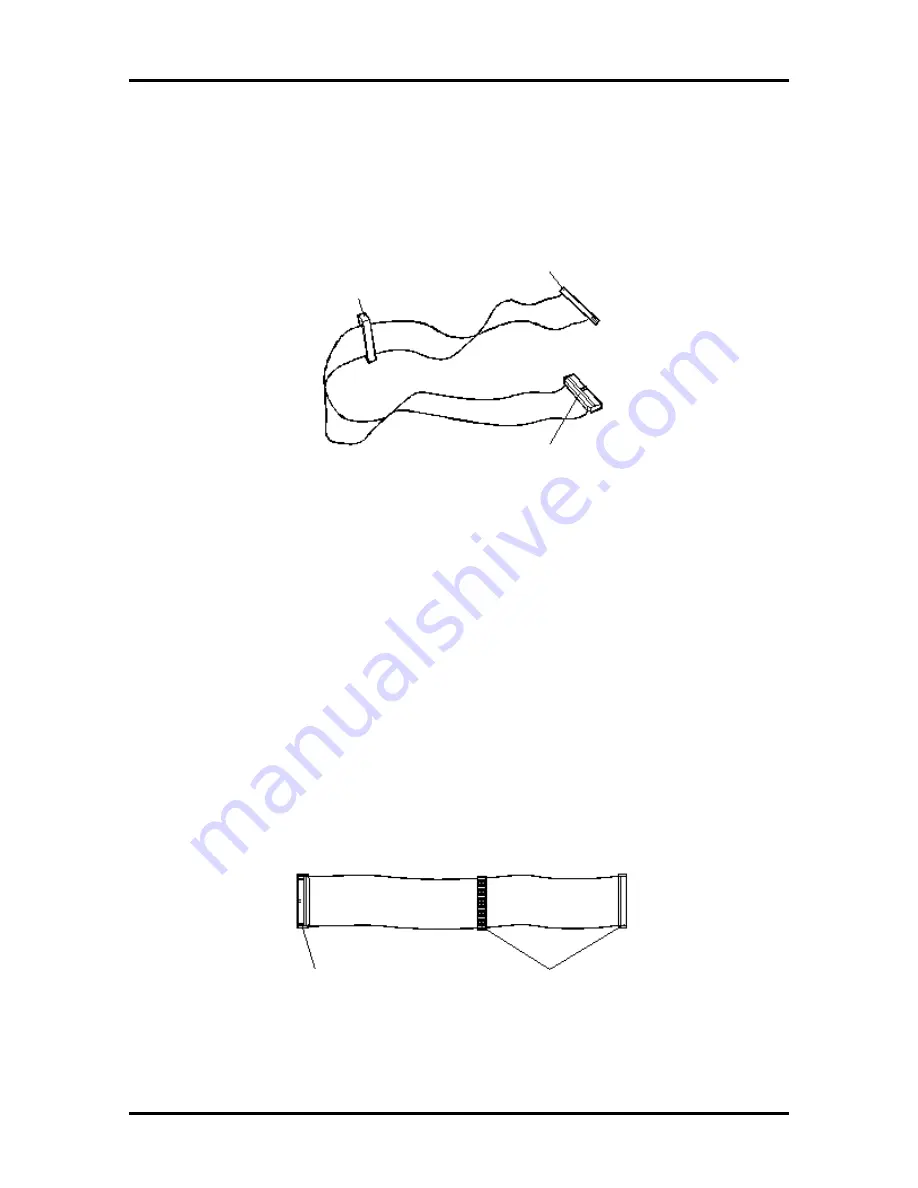
The following figure shows the standard three-connector diskette drive signal cable.
Figure 3-13 Diskette Drive Signal Cable
IDE Signal Cables
Hard disk systems come with a three-connector IDE interface cable attached to the primary
IDE connector. Multimedia systems come with a second IDE cable connected to the
CD-ROM reader and to the secondary IDE connector.
Each IDE connector on the system board supports two IDE devices. The addition of an
IDE device to an IDE connector does not require the replacement of the existing IDE signal
cable.
The following figure shows a typical three-connector IDE signal cable. If the IDE cable is
not keyed with a connector tab, align the colored edge of the cable with the pin 1 side of the
drive connector.
Figure 3-14 IDE Cable Connectors
Attaches to 1.2-MB
Diskette Drive
Attaches to 1.44-MB
Diskette Drive
Attaches to
System Board
Connects to System
Board IDE Connector
Connects to IDE
Devices
Содержание POWERMATE PRO150
Страница 152: ...A 16 Connector Pin Assignments ...
Страница 160: ...B 8 System Board Settings ...


