B-2 System Board Settings
2.
Remove the system unit side panel (see “Removing the Side Panel” in Section 3).
3.
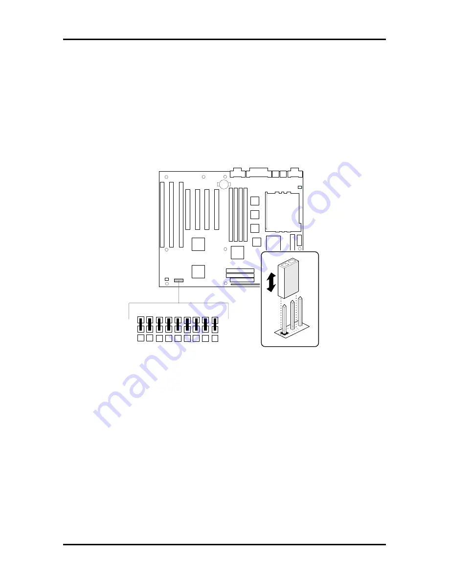
Locate the jumper bank on the system board (see Figure B-1).
4.
Change the switch setting to the appropriate position.
5.
Replace the system unit side panel (see Replacing the Side Panel in Section 3).
The Figure B-1 shows the jumper locations on the system board. Explanations follow the
figure.
OM04 100
A
B
C
DOW N
G
H
I
UP
Figure B-1 System Board Jumper Locations
Содержание POWERMATE PRO150
Страница 152: ...A 16 Connector Pin Assignments ...
Страница 160: ...B 8 System Board Settings ...


