Setup and Operation 2-5
4.
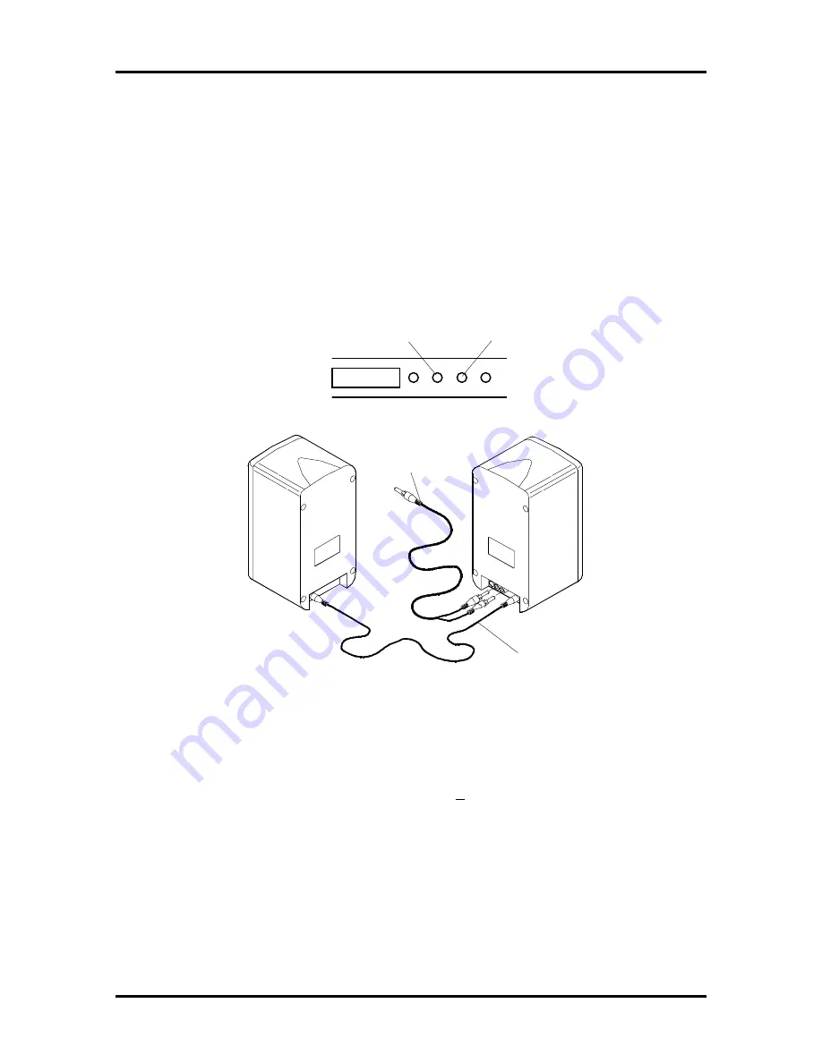
Attach the Y-cable as follows.
n
Insert the red connector into the red jack marked “RIGHT LINE IN” on the
back of the right speaker.
n
Insert the white connector into the white jack marked “LEFT LINE IN” on
the back of the right speaker.
n
Insert the other end of the cable into the Line Out jack on the rear of the
system unit.
Figure 2-6 Attaching the Y-Cable
5.
Locate the AC adapter.
6.
Plug the AC adapter into the jack marked “+15 DC” on the back of the right
speaker.
To System Unit
Line Out Jack
(connector with
two rings)
Right Speaker
Line Out Jack on
Sound Board
Microphone Jack
on Sound Board
Содержание POWERMATE PRO150
Страница 152: ...A 16 Connector Pin Assignments ...
Страница 160: ...B 8 System Board Settings ...


