


4-46 Configuring Your Server
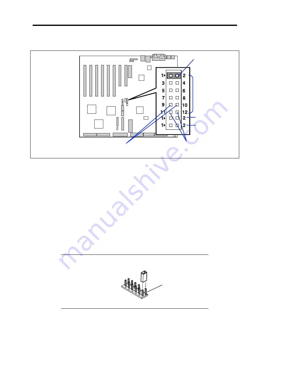
The following figure illustrates the jumper switch location.
Pins for protecting/clearing the passwords
Short-circuit these two pins to clear the passwords.
Open these two pins to protect the passwords (factory-set).
Pins for protecting/clearing the CMOS data
Short-circuit these two pins to clear the CMOS data.
Open these two pins to protect the CMOS data (factory-set).
7.
Reassemble the server and press the POWER switch.
8.
Run BIOS setup utility to reconfigure the baseboard.
9.
Save and exit the utility.
10.
Restore the jumper switch setting and power on the server for reconfiguration.
NOTE:
Place the clip over the jumper pins 1 and 2 after use to keep
the pin.
Pins 1 and 2.
Pins for protecting/clearing
the passwords.
Use the clip over
pins 1 and 2.
Pins for protecting/clearing
the CMOS data.
JP4
JP5
JP6
Содержание Express5800/140Rc-4
Страница 10: ...iv This page is intentionally left blank ...
Страница 34: ...1 18 Notes on Using Your Server This page is intentionally left blank ...
Страница 93: ...Setting Up Your Server 3 21 21 Install the front bezel Now the installation is completed ...
Страница 110: ...3 38 Setting Up Your Server This page is intentionally left blank ...
Страница 196: ...5 40 Installing the Operating System with Express Setup This page is intentionally left blank ...
Страница 286: ...8 48 Troubleshooting This page is intentionally left blank ...
Страница 360: ...9 74 Upgrading Your Server This page is intentionally left blank ...
Страница 362: ...A 2 Specifications This page is intentionally left blank ...
Страница 400: ...F 4 Product Configuration Record Table This page is intentionally left blank ...


