background image

10 | 

P a g e


INSTALLING A REAR VIEW CAMERA YOU SHOULD  USE THE UCT84/NTV-KIT 297 and the UCT differential 
camera adapter/NTV-KIT314 instead.  

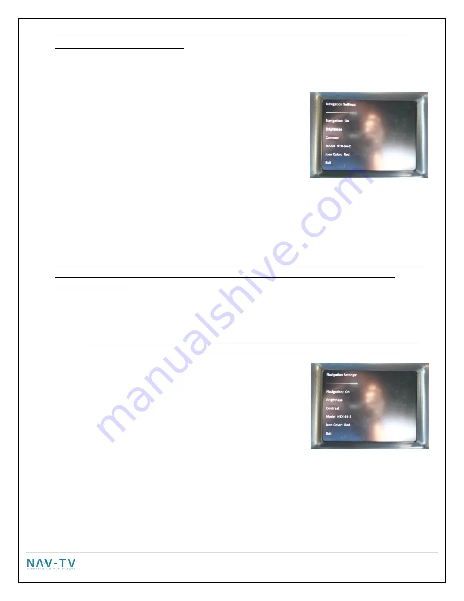
Adjusting the navigation settings (if installed) 


Press the “Navigation input settings” soft key.


Adjusting the input: 

o


Touch the  “Navigation” soft key 

o


Every press of the icon will change the input: OFF & ON. Only the 
RGB input is available. The input image will not be displayed in 
the back ground. Make sure that the "input" setting is selected 
to "ON". 

Adjusting brightness:  

o


Touch the “Brightness” soft key. 

o


Press the “-“or “+” soft key to adjust the image in 10% increments.  

o


Press the “Exit” soft key. 

Adjusting Contrast: 

o


Touch the “Contrast” soft key. 

o


Press the “-“or “+” soft key to adjust the image in 10% increments.  

o


Press the “Exit” soft key. 


!DO NOT SELECT EXIT AT THIS POINT FROM THE NAVIGATION INPUT SETTINGS SCREEN! YOU MUST SELECT 
THE PROPER NAVIGATION SYSTEM AS WELL AS THE COLOR ICON AND SCREEN RESOLUTION IN THE 
FOLLOWING SECTION! . 

Selecting the proper Navigation system 


o


This step is CRITICAL as it determines the communication protocol of the navigation system. If you 
choose the wrong navigation system the touch screen will not control the navigation system.  

o


Touch the  “Model” soft key to switch between 1 of 4 compatible 
navigation options. There are 4 navigation options available: 
NTX54-1, NTX54-2, KNA-G610 and WP.   

o


NTX54-1

: This setting is NOT USED on the 8.4" and is only for 

future use. The NTX54-1 navigation system is not compatible 
with the 8.4" monitor. If you are attempting to install a 
navigation system in a vehicle with an 8.4" screen  and the 
NTX54 has a white label that says "NTX54-1",  STOP and contact 
the establishment you purchased the unit from and have the navigation exchanged. 


o


NTX54-2

: The NTX54-2 is a communication setting only. It is used with either the NTX54-2 or NTX54-3 

navigation system on the 8.4". When using a NTX54-2 or NTX54-3 select NTX54-2 as the correct model. 
The NTX54-2 & NTX54-3 have a white sticker on the bottom for identification. NOTE: The NTX54-2 is 
used ONLY in 8.4" vehicle that have factory Bluetooth. The NTX54-3 can be used either with an external 
speaker OR in vehicles with factory Bluetooth. 

The loop on the plug that plugs in at the NTX54-2 or 

NTX54-3 navigation brain MUST BE INTACT and NOT CUT when using an 8.4" monitor


Содержание NTX-54

Страница 1: ...iat UConnect Touch 4 3 8 4 systems Overview Adds touch screen controlled navigation to vehicles without factory navigation Provides a rear view camera solution for both the 4 3 and 8 4 UConnect Touch radios camera not included Allows DVD video to be viewed while the vehicle is in drive only on 8 4 DVD equipped systems Product Description 1 UCI 11C interface module 2 Radio T harness 3 Included afte...

Страница 2: ...rness 18 pin plug Hh Navigation harness 24 pin plug USB update port White connector Plug the factory white cable taken from the back of the factory monitor here Black connector Plug the included aftermarket black LVDS end in here Plug the other white end into the factory monitor Rear view camera input 8 pin plug LED activity lights ...

Страница 3: ...o Left IN 12 EMPTY 24 Audio Right IN 18 pin Radio T Harness connector 1 12v Power 10 Ground 2 Audio Ground OUT Radio 11 Audio Ground IN Car 3 Audio Right OUT Radio 12 Audio Right IN Car 4 Audio Left OUT Radio 13 Audio Left IN Car 5 1A 12v OUTPUT OUT 1 14 1A 12v OUTPUT OUT 2 6 Infotainment CAN HI Radio 15 Infotainment CAN LO Radio 7 Infotainment CAN HI Screen 16 Infotainment CAN LO Screen 8 Vehicle...

Страница 4: ...the radio is in the glove box 3 Disconnect the factory white 22 pin connector from behind the radio gateway This connector supplies Power and ground as well CAN communication to the radio 4 In the kit is a 22 pin T harness Connect the removed harness from the radio to the female receptacle of the supplied harness Take care not to bend any of the pins in the female receptacle when inserting 5 Plug ...

Страница 5: ...input is on the back of the radio head b Video 1 2 3 Used for an aftermarket camera input using composite video yellow RCA connection Power connections for the rear view camera must be made at the cigarette lighter 14 If installing navigation into the system proceed to the navigation installation section Otherwise continue to step 15 15 After all the connections are made securely mount the UCI mod...

Страница 6: ...metal surface 9 Connect the antenna to the jack labeled GPS ANT on the navigation unit 10 Return to step 15 in the UCI installation instructions and then proceed to the SETTINGS section for your screen size Settings 4 3 Monitor Adjusting the rearview camera settings PRIOR TO ADJUSTING ANY SETTING AFTER THE INITIAL INSTALLATION TURN THE VEHICLE OFF CLOSE ALL DOORS THE HOOD AND TRUNK AND LOCK THE VE...

Страница 7: ...tly video 1 2 3 are not supported Adjusting brightness o Touch the Brightness soft key o Press the or soft key to adjust the image in 10 increments o Press the Exit soft key Adjusting Contrast o Touch the Contrast soft key o Press the or soft key to adjust the image in 10 increments o Press the Exit soft key o If only a camera is being installed and you turned the input to off make sure to select ...

Страница 8: ...e current software revision The current software version is dated September 10 2012 If your software is older than September 10 2012 there is a free software update available at http navtv com page 19 downloads html labeled UCI 11C_Garmin updater 9 10 2012 A REV3 board will show hardware as 3RO and a REV5 will show 5RO Press the Exit soft key to return to the main menu Completing the Setup Procedu...

Страница 9: ... The differential input at the UCI IS NOT USED WITH THE 8 4 monitor o IF NO CAMERA IS BEING INSTALLED SELECT OFF AND THEN EXIT o IF THE VEHICLE HAS A FACTORY CAMERA YOU MUST SELECT HEAD UNIT OR THE CAMERA WILL NOT FUNCTION AFTER INSTALLATION AND YOU WILL BE REQUIRED TO FOLLOW THESE STEPS AGAIN o If installing the Charger Cam also select Head Unit The Charger Cam installs at the back of the radio n...

Страница 10: ...ication protocol of the navigation system If you choose the wrong navigation system the touch screen will not control the navigation system o Touch the Model soft key to switch between 1 of 4 compatible navigation options There are 4 navigation options available NTX54 1 NTX54 2 KNA G610 and WP o NTX54 1 This setting is NOT USED on the 8 4 and is only for future use The NTX54 1 navigation system is...

Страница 11: ...is used for the Dart NOTE WE HAVE DETERMINED THAT SOME DART VEHICLES ACTUALLY REQUIRE THE RED JOURNEY SETTING INSTEAD OF DART IF AFTER INSTALLATION AND TESTING THE NAVIGATION SCREEN APPEARS TO BE SHRUNK TRY SELECTING RED JOURNEY AND PROCEED WITH THE FOLLOWING STEPS Once the proper icon has been selected press Exit to exit the Navigation input setting screen Changing the Video in motion settings Pr...

Страница 12: ...de out Once the vehicle is shifted out of REVERSE the image will fade into the previous mode or screen Do not rely completely on the rear camera image periodically check your surroundings for obstacles Navigation 4 3 monitor To display navigation press the Screen Off button This will display the navigation home page To exit navigation press the Screen Off button again Audio prompts will be heard t...

Страница 13: ...nplug the white LVDS cable at the back of the monitor and plug it into the white port on the UCI Then plug the BLACK end of the included LVDS cable with a white and a black end into the UCI Now plug the white end of the included cable into the monitor Check for factory pass through If good proceed to programming A2 If A1 didn t solve the problem and it is a REV5 board have them remove one end and ...

Страница 14: ...try Make sure to select exit and exit again P9 Selections are not being stored correctly A1 You are not selecting exit and exit again A2 On some vehicles it requires a CAN reset before some settings will stick correctly Do a CAN reset and try again P10 I installed the Garmin or Kenwood system into a 4 3 and i get a distorted navigation picture A1 Cut the wire in pin 8 on the Garmin harness and ret...

Отзывы: