


Chapter 4
Theory of Operation
4-6
ni.com
a temperature sensitivity that counteracts the thermal expansion coefficient
of the test specimen. The STC number approximately equals the thermally
induced change in strain with change in temperature and is expressed in
units of microstrain per degree Fahrenheit. For example, if the test
specimen is aluminum, use a gauge with an STC number of 13.0. If the test
specimen is steel, use a gauge with an STC number of 6.0.
To minimize temperature drift errors in the wiring, use the three-wire
connection shown in Figure 2-3,
Quarter-Bridge I Circuit Diagram
The wires connected to pins P+ (pin 2) and QTR/SCB (pin 9) carry the
same current and are on opposite sides of the same element of the bridge.
Therefore, any temperature-related changes in voltage drop across
R
L
caused by temperature variation of the leads cancel out, leaving
V
CH
unchanged. The voltage drop across the lead resistance on a quarter-bridge
type I configuration is uncompensated in hardware. It is important to
accurately determine the gauge lead resistance and enter it in MAX or in
the application software equation so the software can compensate for the
voltage drop.
You can neglect lead resistance (
R
L
) of the wiring if shunt calibration is
performed or if lead length is very short (
∼
<10 ft), depending on the wire
gauge. For example, 10 ft of 24-AWG copper wire has a lead resistance of
0.25
Ω
.
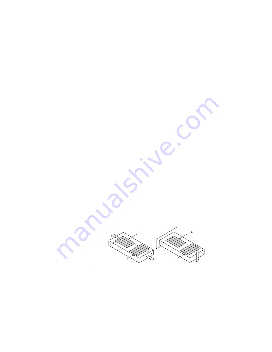
Quarter-Bridge Type II
This section provides information for the quarter-bridge strain-gauge
configuration type II. The quarter-bridge type II measures either axial or
bending strain. Figure 4-4 shows how to position a strain-gauge resistor in
an axial and bending configurations. Figure 4-5 shows the quarter-bridge
type II circuit wiring diagram.
Figure 4-4.
Quarter-Bridge Type II Measuring Axial and Bending Strain
R
4
(+ )
R
3
R
4
(+ )
R
3
Axial
Bending


