Chapter 4
Signal Connections
©
National Instruments Corporation
4-3
VSYNCIN±
Use VSYNCIN± when the 1408 device is in external lock mode. VSYNC is a
synchronization pulse generated at the beginning of each video frame that tells
the video monitor when to start a new field. You can set VSYNCIN in TTL or
RS-422 mode depending on jumper W3 configuration. In RS-422 mode, both
and VSYNCIN– receive the VSYNC signal. The VSYNCIN
polarity is programmable.
CSYNCIN±
Use CSYNCIN± when the 1408 device is in CSYNC external mode. CSYNC
is a signal consisting of horizontal sync pulses, vertical sync pulses, and
equalizing pulses only. You can set CSYNCIN in TTL or RS-422 mode,
depending on jumper W3 configuration. In RS-422 mode, both
and CSYNCIN– receive the CSYNC signal. The CSYNCIN polarity is
programmable.
CSYNCOUT
CSYNCOUT is a TTL output of the internal CSYNC signal. In CSYNC
external mode, CSYNCOUT maps directly to CSYNCIN. In standard mode,
the synchronization circuitry of the 1408 device generates CSYNCOUT.
TRIG<3..0>
Triggers <3..0> are TTL I/O lines used to start or stop an acquisition or output
an acquisition status. You can program the triggers to be rising- or falling-edge
sensitive. You can also program the triggers to be programmatically asserted or
unasserted similar in function to a digital I/O line. You can program
TRIG<3..0> to reflect the following status bits:
Status Bit
Description
AQ_IN_PROGRESS
Signals an acquisition in progress
AQ_DONE
Signals an acquisition is completed
VSYNC
The appropriate VSYNC signal
HSYNC
The appropriate HSYNC signal
PCLK
The A/D sampling signal
Connect a FIELD signal to TRIG3 when the 1408 is in external lock mode with
an interlaced camera.
GND
GND is a direct connection to digital GND on the 1408 device.
+5V
+5V is a fused connection to +5 V on the 1408 device that allows you to power
external triggering circuitry with up to 100 mA.
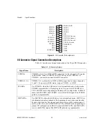
Table 4-1.
I/O Connector Signals (Continued)
Signal Name
Description


