Chapter 2
Configuration and Installation
©
National Instruments Corporation
2-7
Figure 2-4.
Configuring VIDEO0 with Jumper W1
Video channels 1, 2, and 3 are always in differential mode. To take an RSE
measurement on these channels, tie the negative terminal of the connector
to ground (Pin 9 on the 25-pin DSUB connector). See Chapter 4,
, for more information on pin assignments.
External CLK and Synchronization Input Mode
The external PCLK, VSYNC, HSYNC, and CSYNC signals have two
different input modes—RSE (TTL) and DIFF (RS-422) input. In RSE
mode, the input uses one analog input line, which connects to the
synchronization selection circuitry. The negative input to the
synchronization selection circuitry is tied internally to analog ground. For
RSE mode, populate all five sets of jumpers on W3, as shown in Figure 2-5.
In DIFF mode, the input uses two analog input signals. One signal connects
to the positive input of the synchronization selection circuitry while the
other input connects to the negative input of the synchronization selection
circuitry.
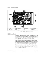
Figure 2-5.
Configuring PCLK, VSYNC, HSYNC, and CSYNC with Jumper W3
a. RSE Mode (Default)
b. DIFF Mode
a. RSE Mode (Default)
b. DIFF Mode


