background image

Napco iSecure Security System                         

All technical manuals are available in PDF format at 

tech.napcosecurity.com


41 

Install the ISEC-EXTANT-KIT (optional) 

The 

ISEC-EXTANT-KIT  Internal  LTE  Extended  Antenna 

Bracket  Kit 

is  installed  inside  the  iSecure  Go-Anywhere 

Hub  to  permit  the  connection  of  an  external  LTE  antenna  to 

improve reception in weak cellular signal areas.  This 

Bracket 

assembly, pictured  in Fig.  1, provides an alternate SMA con-

nection  to  the  LTE  radio,  allowing  the  use  of  Napco 

SLE-

ANTEXT

  antenna  kits.    The  remote-mounted  antenna  is  a 

dual-wideband,  indoor/outdoor  LTE  antenna  that  significantly 

improves  cellular  reception  (

Note: 

  Mount  the 

SLE-ANTEXT 

antenna  before  performing  these  instructions  to  allow  its  im-

mediate  use  after  installing  the 

ISEC-EXTANT-KIT

  and  the 

radio is re-powered).  For details about the SLE-ANTEXT, see 

WI2230,  available  from  the  NAPCO  Technical  Library  at 

tech.napcosecurity.com

.   


INSTALLATION STEPS 

Bracket installation requires flat and Phillips head screwdrivers 

and a cable zip tie (supplied).   


1.  Remove  AC  power  from  the  Go-Anywhere  Smart 

Hub

 by unplugging the AC transformer.   


2.  Separate the Go-Anywhere Hub housing

.  With a flat 

head screwdriver, push in the two tabs at the bottom to 

unhook, then carefully separate the two parts of the Hub 

housing.  

Note:

  Separating the housing disconnects the 

battery.    


3.  Remove  the  top  screw

 at the top of the unit that se-

cures the front LED Faceplate to the front housing.   


4.  Remove  the  LED  Faceplate

.    From  the  front  of  the 

housing, pull out the LED Faceplate to remove.  . 


5.  On  the  inside  of  the  LED  Faceplate

,  remove  the 

screw that secures the 

right side 

light pipe (when view-

ing from the rear) as shown in Fig. 2. 


6.


While  keeping  the  light  pipe  in  place

,  position  the 

Bracket  on  top  of  the  light  pipe  boss  .    Re-install  the 

screw removed in step 6 and install an additional screw 

as shown in Fig. 2.   


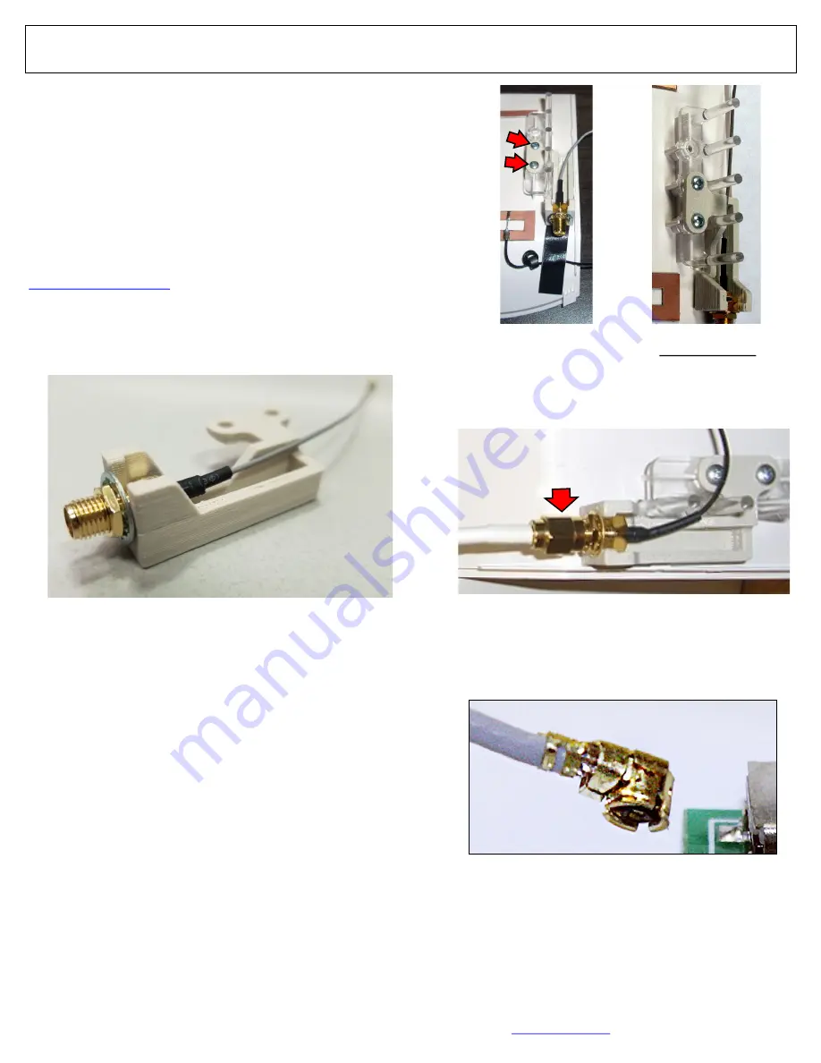
7.  Connect the  Antenna (SMA female) cable

 end to the 

male  threaded  end  of  the  Bracket  (see  Fig.  3).    Route 

the cable through the Hub housing.   


8.


Insert  the  very  small  Antenna  Plug

  located  at  the 

end of the Bracket (shown in Fig. 4) into the correct PC 

board sockets as described in Fig. 5:   


Be  sure  the  plug  freely  rotates  but  remains  connected.  

If  this  plug  should  disconnect,  simply  insert  and  press 

firmly  until  connected.   

Handle  wire  with  care;  do  not 

twist, create sharp bends or apply excessive force

.  


9.


Replace  the  LED  Faceplate

.    Be  careful  to  ensure 

both Antenna Plugs remain connected to their sockets.  


Fig. 4:  Antenna Plug  

Fig. 1:  Antenna Bracket Assembly ("Bracket") 

Fig. 2:  Two views of rear LED Faceplate:  Secure Bracket to 

right side with two screws (arrows) on top of light pipe.   

Fig. 3:  Connect the cable to the Bracket. 

Содержание iSecure ISEC-EXTANT-KIT

Страница 1: ...arefully separate the two parts of the Hub housing Note Separating the housing disconnects the battery 3 Remove the top screw at the top of the unit that se cures the front LED Faceplate to the front...

Страница 2: ...ose the two parts of the Hub housing routing the cable out the rear access door see Fig 9 Be sure not to crimp the wire between the PCB and the housing Closing the two parts of the Hub housing will re...

Страница 3: ...Receiver trouble due to excessive radio noise in area Try relocating the Smart Hub Otherwise call for service Rapid Flicker Transmissions in progress Flashing 900MHZ peripheral download Status Off No...

Страница 4: ...e ISEC WL TOUCH press and hold the appropri ate FIRE AUX or PANIC button respectively see the Us er s Guide for details By default Emergency Buttons are enabled for all keypads to disallow their use s...

Страница 5: ...R FUNCTION Select Instant or Interior When armed STAY usually when sleeping and you want the motion to ignore movement within the home select Interior If you want the sensor to immediately trigger an...

Страница 6: ...it sensor ID for the device 4 DESCRIPTION Type the sensor descrip tion you wish to appear on the keypad display AREA Default 1 See the key pad Operating Guide for the definition of Area SENSOR FUNCTIO...

Страница 7: ...sor For example use for an interior door that will be in use when armed STAY but protected when armed AWAY Instant Allows for an immediate alarm when activated providing instant protection while you o...

Страница 8: ...ON Type the sensor descrip tion you wish to appear on the keypad display SENSOR TYPE Select Smoke Sensor SENSOR FUNCTION Smoke is automatically selected when Smoke Sen sor is select ed as the SENSOR T...

Страница 9: ...on the keypad display SENSOR TYPE Select Heat Sensor SENSOR FUNCTION Heat is auto matically select ed when Heat Sensor is se lected as the SENSOR TYPE SENSOR ID Type in the 7 digit sen sor ID for the...

Страница 10: ...or DESCRIPTION Type the sensor descrip tion you wish to appear on the keypad display SENSOR TYPE Select Carbon Monoxide SENSOR FUNCTION CO Alarm is automatically selected when Carbon Mon oxide is se l...

Страница 11: ...the following Instant Allows for an immediate alarm when the panic button is pressed providing instant protection 24Hr Zone Audible Provides protection at all times whether or not the sys tem is armed...

Страница 12: ...e Select to disable the designated key Key 3 and or Key 4 Panic Pressing the designated key causes the siren to sound and sends a panic report to the central station Instant Pressing the designated ke...

Страница 13: ...wered by an AC power supply plugged into a 120VAC unswitched wall outlet or with batteries Select the power type used by your siren NAME Type the siren description you wish to appear on the keypad dis...

Страница 14: ...ired zone to the RF ID of the supervised 900MHz wireless zone up to 8 zones for each ISEC WL MODULE In the TAKEOVER screen shown below for the Takeover Module added previously program each column as d...

Страница 15: ...mn 3 To add a new Code click in a blank USER CODES field and enter the new User Code up to 6 digits To erase or change an existing Code simply clear or re enter the User Code 4 Add a check to either o...

Страница 16: ...Download Security Code for all accounts When attempting to establish a connection if this code is forgotten the Master Security Code of the particular Go Anywhere Hub can be used in its place Dealer K...

Страница 17: ...e system installation Video Security Z Wave Remote Access Check to enable access to each service from the Home Screen of the IBR TOUCH WL Smart 7 Wireless IoT Touchscreen Check Remote Access to allow...

Страница 18: ...be needed Users Displays the USER ID NAME EMAIL address of those who can log into the iSecure Cloud Web Portal MASTER is checked for those users authorized to make all changes to the account without...

Страница 19: ...ardware Version refers to the version of the LTE Radio PC board that is plugged into the Go Anywhere Hub motherboard This PCB controls the LTE radio communication reporting functions Other iSecure Clo...

Страница 20: ...relocate the Go Anywhere Smart Hub or the device so they are in closer proximity E 05 NN Transmitter Low Battery When an RF device has a weak battery an error E 05 appears The NN is a two digit number...

Отзывы: