


L
NAPCO Security Systems
X
GEM-P3200 Installation Instructions
WI817F 10/05
Page 51
LCD. Keypad indications are reset by the
C
button unless Reset Day Zone With Arm/Disarm is selected.
Trouble on a Fire Zone will be indicated by the “
FIRE/TRBL
” reminder and the sounder. An open circuit (trouble) will cause a flash-
ing “
FIRE
” display and a pulsing sounder after a 15-second delay. (A short circuit will cause an alarm condition: steady-on “
FIRE
” dis-
play and pulsing sounder). The
C
button will silence the sounder. Clear the trouble, then press the
C
button once again.
The keypad will reset after a brief delay.
Trouble on Open
Trouble on Short
Trouble on Night Open
(Not for UL installations)
Trouble on Open will identify an open circuit on a loop as a trouble. Trouble on Short will identify a short circuit as a trouble.
Trouble on Night Open, which will identify an open circuit on a normally-closed zone while armed as a trouble condition (not an
alarm), is intended for use with a Napco Monitor-Series dual-technology sensor. While there will be no indication at the keypad, any
of these trouble conditions can be reported if Report Trouble is programmed as well. See Sensor Watch.
Trouble/Trouble Restore Telco 1/Telco 3
See Report Telco 1/Telco 3
Trouble/Trouble Restore Telco 2
See Backup Report on Telco 2
Two-Digit Format
See Data Format
Two-Wire Smoke Detectors
See Smoke Detectors
Unvacated Premises:
Convert from Away to Stay based on no egress through exit door. Default is enabled. (GEM-P3200 panel--
This feature is AUTOMATIC INTERIOR BYPASS). The panel uses the existing programmable feature "Auto Interior Bypass". This
feature must be enabled in CP-01 installations. This feature is enabled in the factory program and it is also enabled when "Enable
CP-01 Features" is selected in the Easy Program Menu. (Address 2421, Bit 0).
User Codes/Authority Levels/Access Bytes
User Closing and Opening Reports by Telephone Numbers
Enable User Code by Area
Up to 48 six-digit User Codes are programmable, each with its dedicated Authority Level and Access Byte. (The Authority Level
comprises an Option Code). Refer to Programming Manual WI818 or WI1184 for descriptions of levels and options.
If reporting to a central station, program User Closing and Opening Reports by Telephone Numbers. In multiple-area systems,
program Enable User Code by Area.
Unsupervised Transmitters
(Programmable with PCD-3000 Software Only) Transmitters can now be unsupervised by programming a “9” in place of point
number “1”.
NOTE:
All points of that transmitter will be unsupervised.
Veri-Phone™
Silence All Outputs During Audio Session
Veri-Phone Zones Priority Over Alarms
Veri-Phone Zones Trip Auxiliary Output
If Silence All Outputs During Audio Session is selected, all output relays will turn off whenever an active low is applied to control-
panel Lug E19 (Listen In). Connect Veri-Phone Terminal 16 (INHO) to Lug E19.
Note:
Do not program Keypad Sounder on Alarm
for Listen-In Zones.
If Veri-Phone Zones Priority Over Alarms is programmed and an active low is applied to the panel's Listen-In Lug (E19), any sub-
sequent alarm reports (except fire alarms) generated during an audio session will be delayed until the end of the session. (Whenever
a listen-in session is in progress, the Veri-Phone will output an active low at its INHO Terminal (16) and Lug E1.)
Program Veri-Phone Zones Trip Auxiliary Relay to have selectable Listen-In Zones. Connect Veri-Phone Terminal 14 (TRIGH)
to control-panel Terminal 8 (AUX. N/O). Program the zone or event for Auxiliary Relay. Do not use the Auxiliary Relay for any other
purpose.
Veri-phone Trips Fire Output
To have selectable Listen-In Zones, use the Fire Output to trigger the Veri-Phone. Connect Veri-Phone Terminal 13 (TRIGL) to
control panel Lug E9 (Fire Output). Program the zone or event for Fire Output; do not use the Fire Output for any other purpose.
NOTE:
Veri-phone trips Auxiliary Relay and Veri-phone trips Fire Output cannot be enabled together. The Auxiliary Relay can be
used for Keyfob Chirp on arming and disarming.
Watch Mode
(by Area) See Day Zone
Wireless Trouble Reporting by Zon
e
All reports of Wireless trouble (Transmitter Low Battery, Transmitter Tamper, Transmitter Su-
pervisory Failure) to central station will identify identifying the zone of the transmitter.
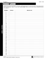
GLOSS
A
RY
Содержание Gemini GEM-P3200
Страница 58: ...X GEM P3200 Installation Instructions L NAPCO Security Systems WI817F 10 05 Page 58 NOTES...
Страница 60: ...X GEM P3200 Installation Instructions L NAPCO Security Systems WI817F 10 05 Page 60 GEM P3200 WIRING DIAGRAM...
Страница 66: ...X GEM P3200 Installation Instructions L NAPCO Security Systems WI817F 10 05 Page 66 Notes...
Страница 67: ...L NAPCO Security Systems X GEM P3200 Installation Instructions WI817F 10 05 Page 67 Notes...


