


L
NAPCO Security Systems
X
GEM-P3200 Installation Instructions
WI817F 10/05
Page 21
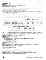
Configuring the GEM-RP2ASe2/GEM-K2AS and GEM-RP3DGTL/GEM-K3DGTL Keypads
Up to 7 GEM-RP2ASe2/GEM-K2AS and/or GEM-RP3DGTL/GEM-K3DGTL keypads may be connected to the panel
(Keypads 1–7). Each must be configured for a keypad address. In addition, the keypad may be configured to disable (a)
touchpad backlight; (b) LCD backlight; and (c) entry sounder. Keypads are configured by the proper selection of jump-
ers. Refer to the label on the circuit board insulation paper for jumper locations and a summary of settings. For the
GEM-RP4RFC/RP4C and GEM-K4RF/GEM-K4 keypads, see their respective installation instructions listed on page 8.
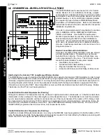
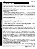
KEYPAD ADDRESS
If more than one keypad is in-
stalled:
Each must be assigned a
unique address (that is, no two key-
pads may be numbered alike).
Keypads must be addressed
consecutively (that is, missing num-
bers are not permitted).
Only Keypad No. 1 may be used
for programming. (However, for
ease of programming, it is recom-
mended that a GEM-RP1CAe2/
GEM-K1CA be selected as Keypad
#1.)
Assign the keypad address
number by selecting Jumpers
J1–3 in accordance with the ta-
ble at left.
*Note:
(1) Keypads are factory
supplied with no jumpers in-
stalled and as such are auto-
matically configured as Keypad
No. 1. (2) Only one keypad in
the system may be configured
as Keypad No. 1, otherwise
none will function.
TOUCHPAD BACK LIGHT
Cut Jumper A to disable touch pad backlighting to conserve 11mA standby current.
LCD BACKLIGHT
Cut Jumper B to disable LCD backlighting.
DISABLE SOUNDER
Cut Jumper C to disable the sounder. (Do not disable in UL applications.)
NAPCO Security Systems, Inc.
333 Bayview Avenue, Amityville, New York 11701
For Sales and Repairs, call toll free: (800) 645-9445
For direct line to Technical Service, call toll free: (800) 645-9440
Internet: http://www.napcosecurity.com
GEM-RP3DGTL KEYPAD
ADDRESS
NUMBER
KEYPAD NUMBER
1
2
3
4
5
6
7
1
OFF OR
ON
OFF
ON
OFF
ON
OFF
ON
2
OFF
ON
ON
OFF
OFF
ON
ON
3
OFF
OFF
OFF
ON
ON
ON
ON
P
MAY BE USED TO HOLD SPARE JUMPER
1
2
3
P
1
2
3
P
Jumper 1
GEM-RP2ASe2 KEYPAD
P
3
2
1
P
3
2
1
Jumper 1
KEYPAD
NUMBER
ADDRESS JUMPER
1
2
3
PARK
1
OFF OR
ON
OFF
OFF
2
OFF
ON
OFF
3
ON
ON
OFF
4
OFF
OFF
ON
5
ON
OFF
ON
6
OFF
ON
ON
7
ON
ON
ON
MAY BE USED TO
HOLD SPARE
JUMPER
KEYP
A
D
CONFI
G
UR
A
T
ION MOD
E
Содержание Gemini GEM-P3200
Страница 58: ...X GEM P3200 Installation Instructions L NAPCO Security Systems WI817F 10 05 Page 58 NOTES...
Страница 60: ...X GEM P3200 Installation Instructions L NAPCO Security Systems WI817F 10 05 Page 60 GEM P3200 WIRING DIAGRAM...
Страница 66: ...X GEM P3200 Installation Instructions L NAPCO Security Systems WI817F 10 05 Page 66 Notes...
Страница 67: ...L NAPCO Security Systems X GEM P3200 Installation Instructions WI817F 10 05 Page 67 Notes...


