

2202L5JE-DA-C5-N_2015.05.
5 Maintenance and Inspection
Compound 2-stage Screw Compressor
5.5
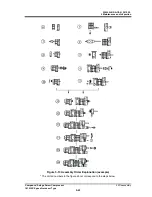
Reassembly
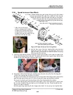
1612LSC Speed Increaser Type
5-45
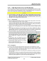
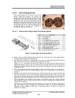
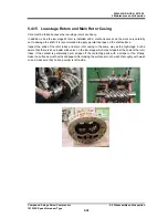
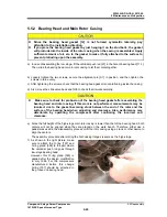
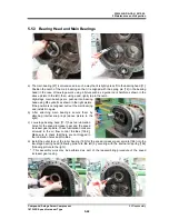
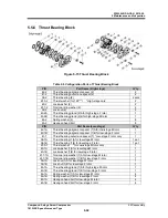
5.5.2 Bearing Head and Main Rotor Casing
Since the bearing head gasket
[12]
is not formed symmetric laterally, pay
attention to the installation direction.
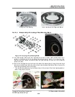
If you place the bearing head gasket by just hanging it on the stud bolts, the gasket
will protrude into the inside of the rotor casing when the casing is assembled. Apply
sufficient amount of oil, etc. to the gasket to make it fully attached to the surface to
prevent protruding upon the assembly.
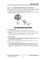
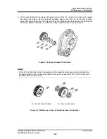
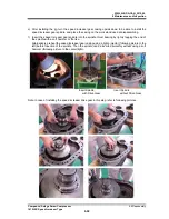
a) In case of assembling the low-stage, fit the unloader push rod [67] in the hole of bearing head [11-1].
Then, slide the bearing head or main rotor casing to let them mate together.
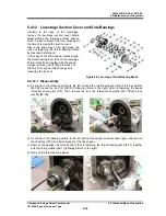
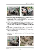
b) Loosely tighten the two screws, secure the alignment pin [3-1] in position, and then tighten the
screws in turn evenly.
c) After tightening the screws, check that the bearing head gasket is not protruding inside the casing.
d)
Also, move the slide valve back and forth to check that it works normally.
Make sure to check for protrusion of the bearing head gasket after assembling the
bearing head and rotor casing. If this work is not performed, measurements may be
incorrect due to the gasket becoming stuck between the end of the rotor and the
surface of the bearing head when adjusting end clearance. Also, performance may
deteriorate by operating the compressor after confirming the incorrect end
clearance.
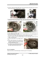
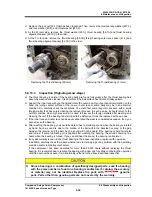
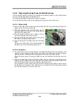
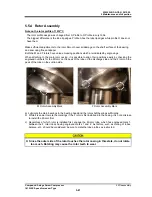
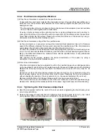
e) Since the full height of the high-stage main rotor casing is lower than that of the bearing head, both
centers will not be aligned when they are placed on the work bench. Therefore, either use a
pedestal as used in the disassembly process or lift the rotor casing using a crane or other device to
align the centers.
The assembly procedure after mating the both casing flanges is same as the high-stage.
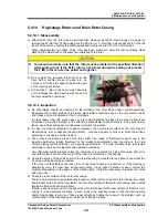
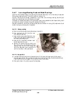
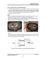
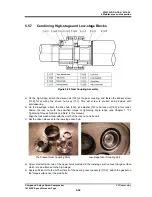
f)
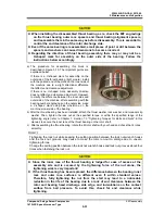
As shown in the right picture, make
sure to attach the O-ring [197] and
O-ring gland [326] to the part where
the unloader push rod goes through
low-stage bearing head.
However, this O-ring gland [326] is
applied after the design modification
in July 1986. For the compressors
manufactured before this change
O-ring [197] should be attached in
the groove on bearing head.