
2202L5JE-DA-C5-N_2015.05.
5 Maintenance and Inspection
Compound 2-stage Screw Compressor
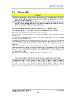
5.5
Reassembly
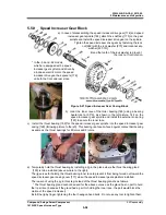
1612LSC Speed Increaser Type
5-56
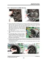
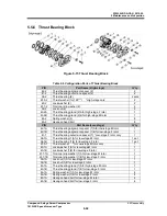
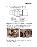
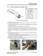
5.5.7 Combining
High-stage and Low-stage Blocks
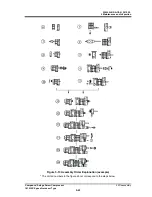
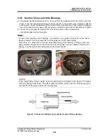
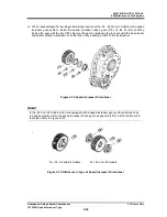
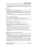
Figure 5-20 Gear Coupling Assembly
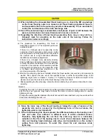
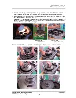
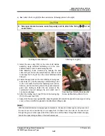
a) On the high-stage, attach the driven hub [153] of the gear coupling, and fasten the M8 set screw
【
159] for securing the driven hub key [157]. This set screw is knurled and provided with
anti-loosening.
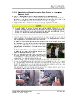
b) On the low-stage, attach the drive hub [152], lock washer [161] and lock nut [160] in this order.
Fasten the lock nut with the specified torque or tightening angle range (see Chapter 7 "7.3
Tightening Torques for Bolts and Nuts" in this manual).
Align the lock washer claw with the notch of the lock nut, and bend it.
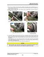
c) Set the driven sleeve onto the low-stage drive hub.
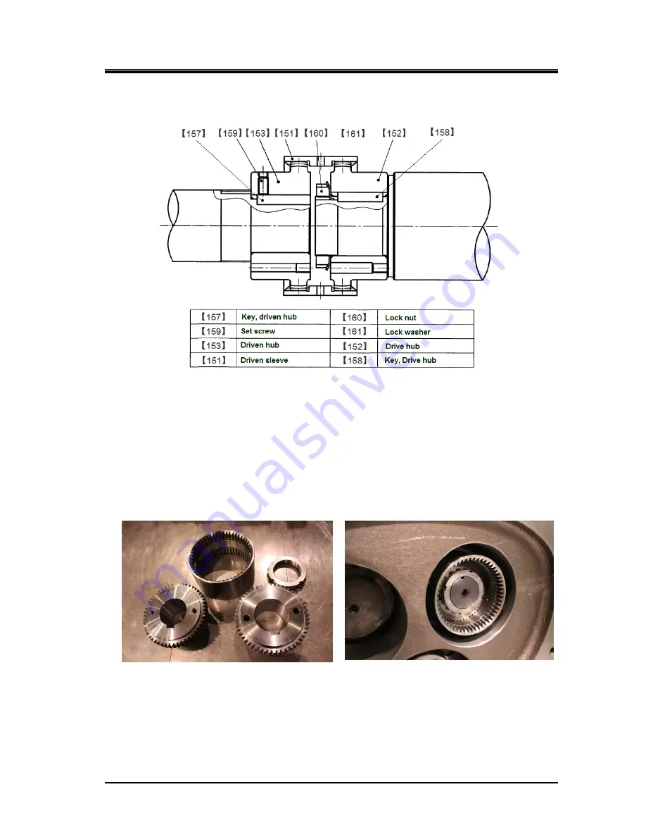
The Present Gear Coupling Parts Low-stage Gear Coupling Part
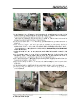
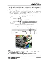
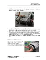
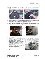
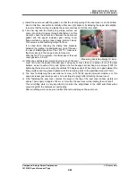
d) Screw stud bolts into two of the upper holes provided in the low-stage suction cover flange surface
which is to be attached to the high-stage.
e) Apply sufficient oil to the both surfaces of the bearing cover gasket (2) [17-2]. Attach the gasket on
the flange surface over the stud bolts.


