
2202L5JE-DA-C5-N_2015.05.
5 Maintenance and Inspection
Compound 2-stage Screw Compressor
5.4 Disassembly and Inspection
1612LSC Speed Increaser Type
5-33
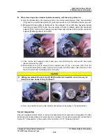
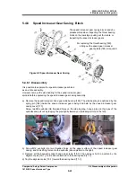
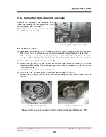
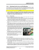
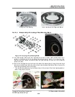
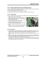
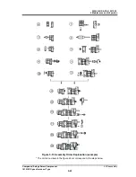
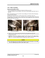
e) And then, unbend the rotation stopper tooth of the lock washer [40-1] (following picture to the left),
loosen the lock nut [39-1] (following picture to the right).
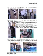
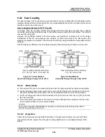
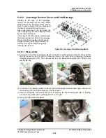
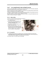
f) Unscrew and remove four hexagon head cap screws which secured the oil injection pipe gland
[164] located in the lower area of the low-stage suction cover (following picture to the left )..
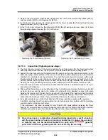
g) Screw a hexagon socket head cap screw [2-1] into the threaded hole of the oil injection pipe, and
pull out it (above picture to the right)..
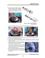
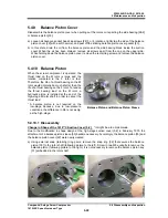
h) Remove all of the hexagon socket head cap screws [2-1] tightening the main rotor casing [1-1] to
the suction cover [5-1]. Next, drive alignment pins [3-1] into the main rotor casing.
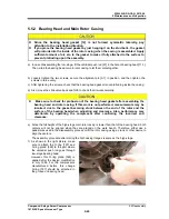
i) Screw in screws [2-1] into the two threaded holes in the rotor casing flange, and then push the
suction cover flange evenly.
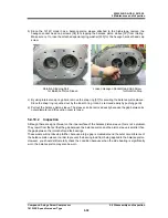
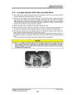
j) When a gap has opened, use a scraper to peel it
up.
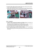
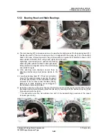
k) When a gap has opened to the length of the
screw, pull out the rotor axis and side bearing
combination by sliding the suction cover on the
work bench parallel with the axis.
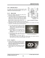
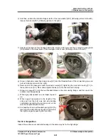
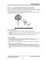
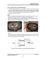
m) It is possible to remove the side bearing [28-1] by
removing the internal snap ring [29-1] (picture to
the right) and gently pushing the rotor side.
5.4.12.2 Inspection
Inspect the suction cover and side bearings in the same way as for the high-stage.


