
2202L5JE-DA-C5-N_2015.05.
5 Maintenance and Inspection
Compound 2-stage Screw Compressor
5.4 Disassembly and Inspection
1612LSC Speed Increaser Type
5-31
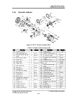
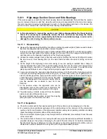
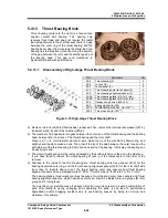
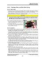
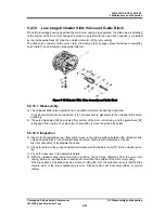
5.4.11 High-stage Suction Cover and Side Bearings
If the work sequence is such that the thrust bearing block is disassembled first and then the suction
cover is removed, there is a risk that, when the suction cover is separated from the main rotor casing,
the rotor may also be pull out and dropped. As such, in the procedure described in this manual, the
suction cover is removed first, and then the thrust bearing is disassembled.
In this procedure to remove the suction cover before disassembling the thrust bearing
block, it is necessary to sufficiently loosen the lock nut that are securing the thrust
bearing while the rotor is supported by both the main and side bearings, in order not to
damage the rotor during the disassembly process.
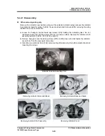
5.4.11.1 Disassembly
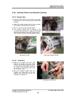
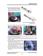
a) Remove the hexagon head bolts [45-2] and the conical spring washers [46-2] that are used to fasten
the thrust bearing gland [43-2], and then remove the gland.
In case of a former model which uses a rotation stopper fitting instead of a conical spring washer,
extend the claw bent plate of the rotation stopper and remove it from the hexagon head blot [46-2],
and then remove the hexagon head bolt and the thrust bearing gland.
b) Unbend the rotation stopper tooth of the lock washer [40-2] holding the lock nut [39-2] which retains
the inner race of thrust bearing [38-2] on the rotor shaft and loosen the lock nut using a lock nut
wrench.
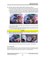
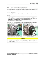
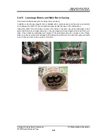
c) As the height of the high-stage main rotor casing is low, the casing is installed like a bridge to
connect between the suction cover and the bearing head. As such, the main rotor casing will be
supported only by one side (i.e., overhang) when the suction cover is removed. To avoid this, either
place squared timbers or use a lifting device to properly support the main rotor casing.
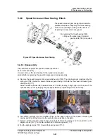
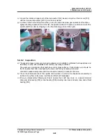
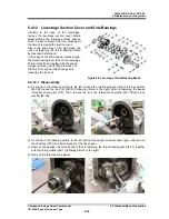
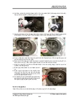
d) Loosen and remove the hexagon socket head cap screws [2-2] that hold the high-stage suction
cover [5-2] and the high-stage main rotor casing [1-2]. e) Since the suction cover gasket [6-2] is
stuck to the flange surface, evenly push the suction cover by screwing two of the removed hexagon
socket head cap screws [2-2] into the jacking threaded
holes in the flange part of the main rotor casing. When a
gap has opened, use a scraper to peel up to one
direction.
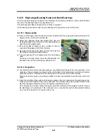
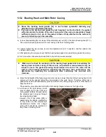
f) At the position where the alignment pins can be
disengaged, remove the suction cover parallel to the
axis with a single pulling motion (picture to the right).
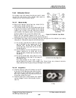
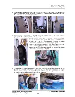
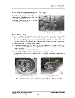
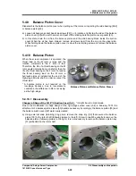
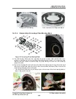
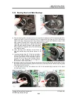
d) The side bearing
【
28-2
】
is press-fit from the balance
piston cover side of the suction cover.
By using internal snap ring pliers, remove the snap ring
[29-2] and push it out from the rotor side.
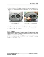
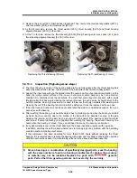
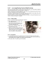
5.4.11.2 Inspection
a) Check the oil inlet path to the balance piston part of the suction cover by spraying air or the like.
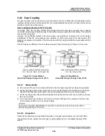
b)
We recommend unconditional exchange of the side bearings on the occasion of the compressor
overhaul, but for confirmation of the compressor condition and system operating condition, carefully
check the sliding part metal surface of the side bearings.
If the metal surface is turned gray or any foreign matter is embedded, also carefully check the wear
of the rotor shaft.
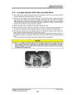
c) The inside surface of the main rotor casing should have no problems because sufficient clearance is
provided. However, if any trace of scraping by the end of the rotor is found, it should be determined
that the thrust bearing is defective. It is also necessary to check the operational condition, such as
whether the system is operated for a long time with a high intermediate pressure.


