
2202L5JE-DA-C5-N_2015.05.
5 Maintenance and Inspection
Compound 2-stage Screw Compressor
5.5
Reassembly
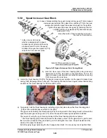
1612LSC Speed Increaser Type
5-63
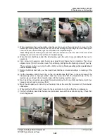
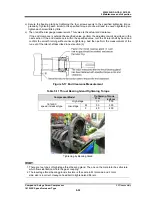
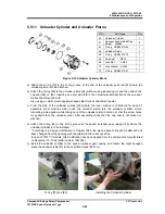
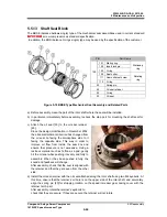
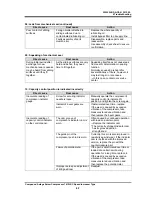
5.5.11 Unloader Cylinder and Unloader Piston
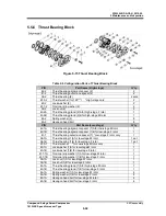
Figure 5-16 Unloader Cylinder Block
a)
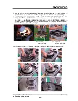
Attach the O-ring [73] to the O-ring groove at the end of the unloader push rod [67] where the
unloader piston is to be attached.
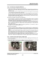
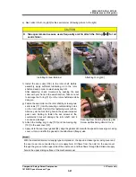
b) Attach the O-ring [65] to the unloader piston [64] without using lubricating oil, and then attach the
cap seal [66] on that. Inserting an outer side fold in the circumferential direction of the cap seal
makes attachment smooth.
Also, using a small smooth spatula-shaped object makes attachment easier.
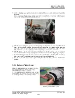
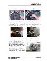
c) From the side of the unloader cylinder [60] where the inner surface is chamfered for ease of
assembly (inner machine side), push the unloader piston into the unloader cylinder, which
lubricating oil is applied, while taking care of the unloader piston direction so that the screw holes
for eyebolts face the unloader cover. After assembly, check that the cap seal is not broken or
pinched.
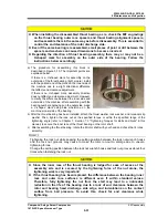
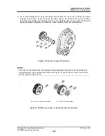
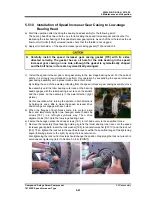
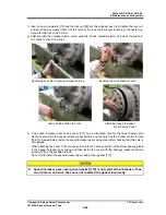
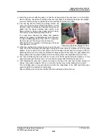
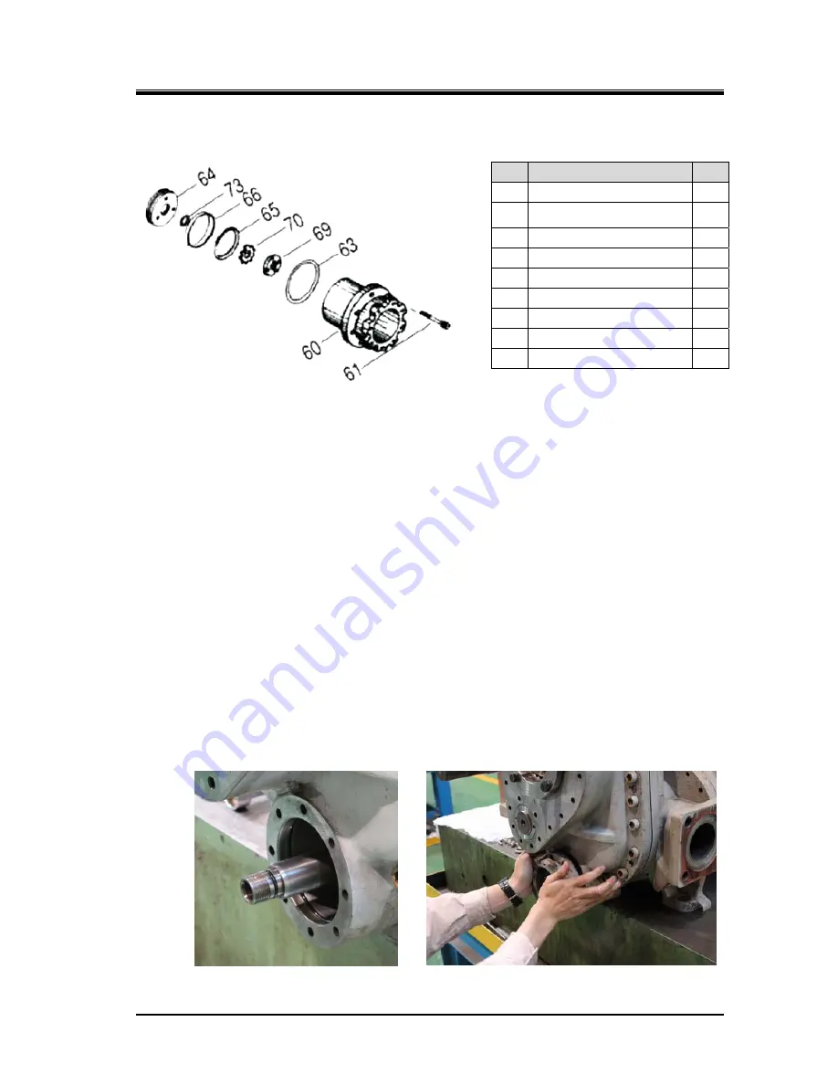
d) Attach the O-ring [63] to the O-ring groove at the speed increaser gear casing [169] where the
unloader cylinder is to be installed.
* According to a design modification in October 1996, the place where O-ring [63] is attached has
been changed from the opening with chamfered to the current position.
In case of 1612**C models, this modification has been applied from the compressor manufactured
on December 13, 1996 (serial number 1622548).
e)
Install the unloader cylinder to the speed increaser gear casing, and fasten the eight hexagon
socket head cap screws [61] to the specified torque (25 N·m).
O-ring [73] and [63] Installing the Unloader Cylinder
P/N
Part Name
Q’ty
60
Unloader Cylinder
1
61
Hexagon Socket Head Cap
Screw
M8X95
8
63
O-ring
JISB2401 G95
1
64
Unloader Piston
1
65
O-ring JISB2401 P75
1
66
Cap Seal BE75
1
69
Lock Nut AN05
1
70
Lock Washer AW05
1
73
O-ring JISB2401 P21
1


