72
M1.3.TIG200PAC.NLFREN 21052019
EN
Operation hints
Arc ignition modes in SMAW
• Low current arc ignition:
This can be also called lift/soft arc ignition. Set the arc ignition current (I1) to be a value
lower than I2 and the machine will enter into low current arc ignition mode. Touch the workpiece with the electrode,
and lift the electrode to the normal position to weld after arc is ignited.
• High current arc ignition:
This can be also called contact/thermal arc ignition. Set the arc ignition current (I1) to
be a value not lower than I2 and the machine will enter into high current arc ignition mode. Touch the workpiece with
the electrode, and normal welding can be carried out without lifting the electrode.
• Electrode selection� See details in table 8�1
Table 8.1 - MMA process specification reference table
Electrode diameter (mm)
Recommended welding current (A) Recommended welding voltage (V)
1.6
30~60
21~23
2.0
50~90
22~24
2.5
80~120
23~25
3.2
100~140
24~26
4.0
140~160
26~28
8�4�2 DC TIG welding
22
/
50
E201 SC-A0
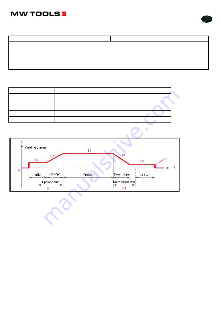
Fig 10.13 DC TIG Current Change Waveform
In DC TIG mode, 8 adjustable parameters are available for this machine. Describe them as below.
Current (I3):
This parameter can be set according to users’ own technical requirements.
Initial current (I1):
It is the current when arc is ignited by pushing the torch trigger, and it should be
set according to users’ own technical requirements. If the initial current is high enough, arc is easier
to ignite. However, it should not be too high when welding thin plate, so as to avoid burn through the
workpiece during arc ignition. In some operation modes, the current does not rise but stay at the
initial current value to preheat the workpiece or illuminate.
Pilot arc current (I5):
In some operation modes, the arc does not stop after current downslope but
stay in the pilot arc state. The working current in this state is called pilot arc current, and it should be
set according to users’ technical requirements.
Pre-flow time:
It indicates the time from the torch trigger being pushed to arc being ignited in
non-contact mode. Commonly it should be longer than 0.5s to make sure that the gas has been
delivered to the welding torch in normal flow before arc ignition. The pre-flow time should be
increased if the gas hose is long.
Post-flow time:
It indicates the time from the welding current being cut off to the gas valve inside the
machine being closed. If it is too long, it will lead to a waste of argon gas; if it is too short, it will result
in the oxidation of weld bead. When in AC TIG or for special materials, the time should be longer.
Upslope time (tr):
It indicates the time spent on current rising from 0 to the preset value, and it
should be set according to users’ technical requirements.
Downslope time (td):
It indicates the time spent on current dropping from the preset value to 0, and
it should be set according to users’ technical requirements.
Tungsten Electrodes Selection: see details in Table 4.2
Table 4-2 TIG Process Specification Reference Table
Electrode Dia
(
mm
)
Recommended Welding Current
(
A
)
1.0
5
~
30
1.6
20
~
90
2.0
45
~
135
Fig. 8.13 DC TIG Current change waveform
In DC TIG mode, 8 adjustable parameters are available for this machine. Describe them as below.
• Current (I3):
This parameter can be set according to users’ own technical requirements.
• Initial current (I1):
It is the current when arc is ignited by pushing the torch trigger, and it should be set according to
users’ own technical requirements. If the initial current is high enough, arc is easier to ignite. However, it should not be too
high when welding thin plate, so as to avoid burn through the workpiece during arc ignition. In some operation modes, the
current does not rise but stay at the initial current value to preheat the workpiece or illuminate.
• Pilot arc current (I5):
In some operation modes, the arc does not stop after current downslope but stay in the pilot
arc state. The working current in this state is called pilot arc current, and it should be set according to users’ technical
requirements.
•
Pre-flow time:
It indicates the time from the torch trigger being pushed to arc being ignited in non-contact mode.
Commonly it should be longer than 0.5s to make sure that the gas has been delivered to the welding torch in normal flow
before arc ignition. The pre-flow time should be increased if the gas hose is long.
•
Post-flow time:
It indicates the time from the welding current being cut off to the gas valve inside the machine being
closed. If it is too long, it will lead to a waste of argon gas; if it is too short, it will result in the oxidation of weld bead.
When in AC TIG or for special materials, the time should be longer.
• Upslope time (tr):
It indicates the time spent on current rising from 0 to the preset value, and it should be set according
to users’ technical requirements.
• Downslope time (td):
It indicates the time spent on current dropping from the preset value to 0, and it should be set
according to users’ technical requirements.
• Tungsten Electrodes Selection: see details in Table 8.2
copyrighted
document
- all
rights
reserved
by
FBC


