71
M1.3.TIG200PAC.NLFREN 21052019
EN
8�4 Welding modes description
8�4�1 MMA
20
/
50
E201 SC-A0
parameters during adjustment and these parameters will change automatically due to different mode’s
condition limits
10.4 Welding Mode Description
10.4.1 MMA
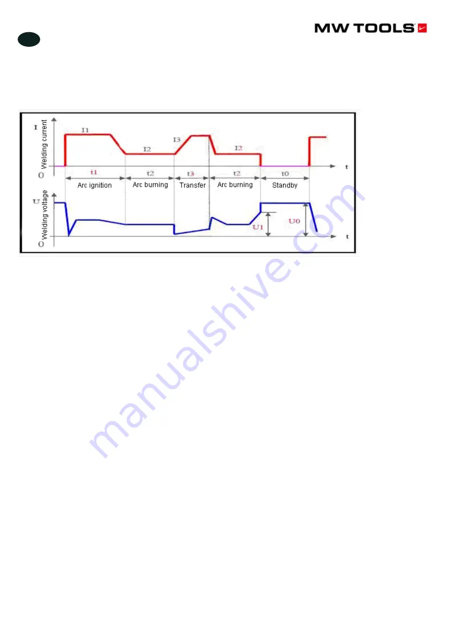
Fig 10.12 Current and Voltage Change during MMA
In SMAW mode, 4 parameters that can be adjusted directly and 1 parameter that can only be adjusted
through programming are available for this machine. Describe them as below.
Current (I2):
This is the welding current when arc is burning, and users can set it according to their
own technical requirements.
Arc force:
It refers to the ascending slope of the current in short circuit, and it is set as the amperage
increased per millisecond in this machine. The current will ascend from the preset value by this slope
after short circuit occurs. (E.g. When the preset current is 100A and the arc force is 20, the current
will be 200A 5ms after short circuit occurs.) If it is still under short circuit when the current increases
to the allowable maximum value 250A, the current will not ascend any more. If the short circuit status
lasts for 0.8s or more, the machine will enter into electrode sticking process: to wait the
Note:
t0—Standby: No welding current; output voltage is the no-load voltage.
t1—Arc ignition: Welding current is arc ignition current (I1).
t3—Arc burning: Welding current is the preset current (I2).
t4—Short-circuit transfer: Welding current is the short-circuit transfer current (I3).
Fig. 8-12 Current and voltage change during MMA
Note:
t0—Standby: No welding current. Output voltage is the no-load voltage
t1—Arc ignition: Welding current is arc ignition current (I1)
t3—Arc burning: Welding current is the preset current (I2)
t4—Short-circuit transfer: Welding current is the short-circuit transfer current (I3)
In SMAW mode, 4 parameters that can be adjusted directly and 1 parameter that can only be adjusted through programming
are available for this machine. Describe them as below.
• Current (I2)
: This is the welding current when arc is burning, and users can set it according to their own technical
requirements.
• Arc force
: It refers to the ascending slope of the current in short circuit, and it is set as the amperage increased per
millisecond in this machine. The current will ascend from the preset value by this slope after short circuit occurs. E.g. When
the preset current is 100 A and the arc force is 20, the current will be 200 A 5 ms after short circuit occurs. If it is still under
short circuit when the current increases to the allowable maximum value 250 A, the current will not ascend any more. If the
short circuit status lasts for 0.8s or more, the machine will enter into electrode sticking process: to wait the disconnection
of the electrode under low current. Arc force should be set according to the electrode diameter, preset current and the
technical requirement. If the arc force is big, the molten drop can be transferred quickly, and electrode sticking seldom
occurs. However, too big arc force may lead to excessive spatter. If the arc force is small, there will be little spatter, and the
weld bead will be shaped well. However, too small arc force may lead to soft arc and electrode sticking. Therefore, the arc
force should be increased when welding with thick electrode under low current. In general welding, the arc force may be
set at 5~50.
• Arc ignition current (I1) and arc ignition time (T1)
: Arc ignition current is the output current of the machine when
the arc is ignited. Arc ignition time is the time the arc ignition current lasts. When in non-contact ignition mode, neither
parameter makes sense. When in high current ignition mode, the arc ignition current is generally 1.5 ~ 3 times the welding
current, and the arc ignition time is 0.02 ~ 0.05 s. When in low current ignition mode, the arc ignition current is generally
0.2 ~ 0.5 times the welding current, and the arc ignition time is 0.02 ~ 0.1 s.
copyrighted
document
- all
rights
reserved
by
FBC


