background image

                                                                                                            ValueCut User Manual 


Optional and Consumable Item List          A-3 


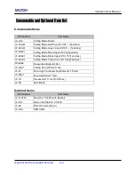
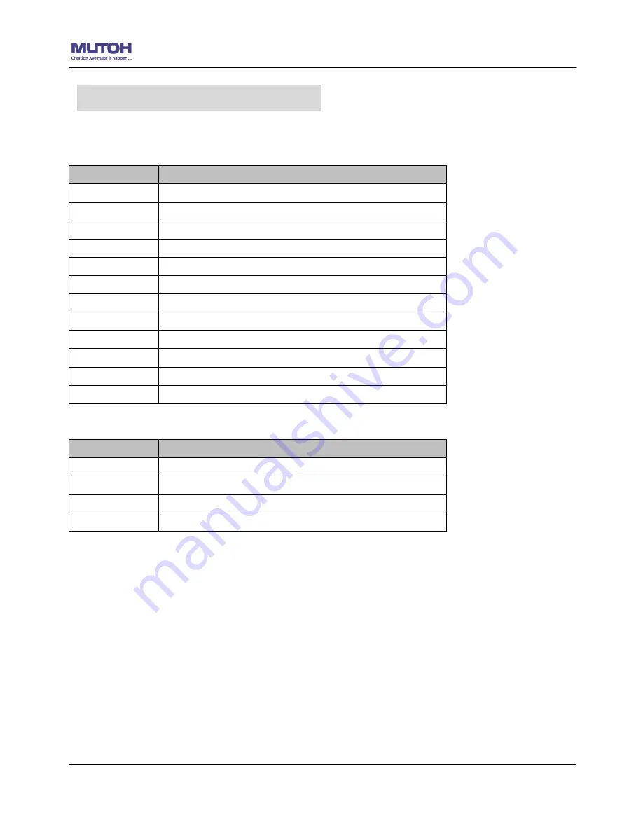
Consumable Items 
 

Part Number 

Item Name 

VC-CHD 

Cutting Blade Holder 

VC-CBRE5 

Cutting Blade Red Cap (45° 0.25

(5pcs/box) 

VC-CBGR1 

Cutting Blade Green Cap (60° 0.5

(1pcs/box) 

VC-CBBU1 

Cutting Blade Blue Cap (60° 0.25)(1pcs/box) 

VC-CBBK1 

Cutting Blade Black Cap (42° 0.175)(1pcs/box) 

VC-CBYE5 

Cutting Blade Yellow Cap (25° 0.25)(5pcs/box) 

PSGB-BK 

Pressurized Ballpoint Pen 

VC-CMAT 

Cutting Pad (W6mm*L10m) 

VC-PT 

Pouncing Tool assembly (Diameter: 1.5mm) 

VC-PMAT 

Pouncing Pad(L=1.5m) 

VC-TW 

Tweezers(L=11cm W=0.85cm ) 

VC-SB 

Safe Blade 

 
Optional Items 

Part Number 

Item Name 

VC-STD600 

Stand for VC-600 (with Basket) 

VC-TBL 

Add-on flat table for VC-600 

VC-RS 

RS-232 Cable (25 pin) 

VC-USB 

USB Cable 


Consumable and Optional Item List


Содержание ValueCut Series

Страница 1: ...V 3 2012 Nov 0BValueCut Series 1 BUser Manual...

Страница 2: ...ify the information contained in this user manual at any time without prior notice un authorized modification copying distribution or display is prohibited All comments queries or suggestions concerni...

Страница 3: ...and instructions below Caution SAFETYPRECAUTIONS For safety concern please always hold the cutter firmly from the bottom while moving it Do not move the cutter by clasping the depression area on both...

Страница 4: ...ght between objects Do not connect the power cable to branching outlet to which other machines are also connected or use an extension cable There is danger of overheating and of mis operation of the m...

Страница 5: ...ValueCutUserManual Important Information ENABLE Pull up bottom to release grip...

Страница 6: ...5 Cutting Pad Installation 2 8 2 11 2 6 Blade Installation 2 13 2 7 Automatic Blade Length Detection 2 15 2 8 Cable Connections 2 17 2 8 1 USB Interface 2 17 2 8 2 Driver Un installation 2 20 2 8 3 RS...

Страница 7: ...aning the cutting Plotter 6 1 6 2 Cleaning the Grid Drum 6 2 6 3 Cleaning the Pinch Rollers 6 2 7 Trouble Shooting 7 1 Non Operational Problems 7 1 7 2 Operational Problems 7 2 7 2 1 LCM Error Message...

Страница 8: ...d d I It te em m Q Qu ua an nt ti it ty y 1 Cutting Plotter 1 2 Stand Set for VC 1300 1800 only Optional for VC 600 2 piece of T shape stand 1 piece of stand beam 18 pieces of M6 screws 1 piece of M5...

Страница 9: ...iece of Safe Blade 1 piece of Cutting Pad for Vinyl cutting 1 piece of Tweezers 1 Oily ball point pen 1 1 3 Product Features The following are the main features of the ValueCut series cutting plotters...

Страница 10: ...and 1 LCM showing messages and menus Cutting Pad provides the protection of blade when the blade is cutting Tool Carriage performs the cutting with the installed blade and pen with AAS module Alignme...

Страница 11: ...oll Holder holds and supplies the roll media for cutting Roll Holder Guide Bushes serve to keep the roll media in place when media is pulled from the roll T Stand supports the cutting plotter Stand Be...

Страница 12: ...Amp AC Power Connector used to insert the AC power cord Power Switch On when switches to I Off to O Figure 1 4 Serial Interface Connector RS232C used to connect the cutting plotter to a computer thro...

Страница 13: ...ily from any direction Keep enough space for the machine accessories and supplies Keep the working area stable avoiding sever vibration Keep the temperature between 15 and 30 60 86o F in the workshop...

Страница 14: ...2 piece of T shape stand 1 piece of stand beam 18 pieces of M6 screws 1 piece of M5 L shape hexagon screw driver 1 piece of Installation Guide for Stand Set Step 2 Remove the plotter body and the acce...

Страница 15: ...gure 2 2 Then the complete picture of stand will be like Figure 2 1 Step 4 Remove the cutting plotter from the carton Position your stand under the plotter and then insert the screws into the holes on...

Страница 16: ...ou could decide roll holder support s position by inserting into different holes Step 6 Place two roll holders into the holes in the roll holder support Figure 2 5 Push the roll holder to the left unt...

Страница 17: ...ValueCut User Manual Installation 2 5 Step 7 Lastly the complete picture will be shown like below Figure 2 6 Figure 2 6...

Страница 18: ...c Foot 4 pieces of M4 screws 12 pieces of M6 screws 1 piece of M4 L shape hexagon screw driver 1 piece of M5 L shape hexagon screw driver 1 piece of M6 L shape hexagon screw driver for adjusting the s...

Страница 19: ...in lateral and position the Roll Holder Assembly beside the bottom of the machine Then insert the M6 screws into the holes of Roll Holder support assembly and tighten them with M6 L shape screwdriver...

Страница 20: ...s 2 pieces of basket rods 1 piece of basket 2 pieces of fixtures for basket arms 8 pieces of M3 screws 1 piece of 2mm L shape hexagon screw driver Step 2 First place the basket arms beside the stand a...

Страница 21: ...See Figure 13 Step 4 Loosen the basket screws from the basket arms Position the basket rod in front of the basket arms and insert the basket screws into the holes on the basket rod and tighten them F...

Страница 22: ...ValueCut User Manual Installation 2 10 Step 5 The complete Media Basket System will be like Figure 2 15 Figure 2 15...

Страница 23: ...e accessory pack Follow the instruction below to install a new cutting pad when the existing pad is worn out Step 1 Carefully remove the cutting pad from the unit Figure 2 16 Step 2 Remove the remaini...

Страница 24: ...alueCut User Manual Installation 2 12 Step 3 Attach the new cutting pad to the groove after unrolling it and removing the backing sheet and the installation process is completed Figure 2 18 Figure 2 1...

Страница 25: ...he bottom of the blade holder Figure 2 22 Step 3 Adjust the blade tip to suitable length by screwing Blade tip adjustment screw clockwise orcount clockwise Figure 2 23 Figure 2 23 Figure 2 22 Tips The...

Страница 26: ...ct pin to eject blade when the blade needs to be replaced Note The blade will lose its sharpness after a period of usage the cutting quality might be affected By increasing the cutting force it might...

Страница 27: ...to adjust the blade length for 0 00mm 5 00mm Figure 2 26 Follow the steps below to adjust the length of the blade 1 Keep the blade tip within the blade holder before you start adjusting 2 Align one o...

Страница 28: ...ich direction CW clockwise or CCW counterclockwise you should turn the adjustment knob EG Turn CW 5 is telling you that you should turn the knob for 5 units clock wisely Figure 2 28 Figure 2 29 5 The...

Страница 29: ...ValueCut build in USB interface are based on the Universal Serial Bus Specifications Revision 1 1 Operation system of Windows 95 Windows NT don t support USB USB driver installation Use the USB One c...

Страница 30: ...nect the USB cable until the installation has completed 3 You can double click the USB icon on the taskbar to make sure the USB device is detected Step 2 Installing the software 1 Put the installation...

Страница 31: ...Manual Installation 2 19 3 Click Next to start the driver installation 4 The installation will take a few minutes to complete and you will see a message below and click on OK upon completion Enjoy you...

Страница 32: ...version successfully Please refer to below steps 1 Right click on the printer to remove the printer from system Printer page 2 After remove from the ValueCut unit right click on any empty space on the...

Страница 33: ...ValueCut User Manual Installation 2 21 3 Select Driver page Select ValueCut 1300 and click on Remove...

Страница 34: ...ValueCut User Manual Installation 2 22 Click on OK Click on Yes The driver installed on PC is completely removed...

Страница 35: ...are package refer to chapter 3 Misc key description 2 8 4 Data Transmitting There are two options to transmit the data from the computer to the cutting plotter Option 1 With proper interface settings...

Страница 36: ...cate the power status light up power on light off power off 4 Arrow Keys To move position select function or change setting ENTER To set item or register the immediately preceding input value PAUSE RE...

Страница 37: ...Force 80 gf OK ENTER use to select ENTER to enable the setting SPEED Speed 72 cm s Select OK ENTER UP Speed 72 cm s Select OK ENTER Quality normal Select OK ENTER OFFSET Offset 0 275 mm OK ENTER DATA...

Страница 38: ...R Offset 0 275 mm OK ENTER 0 000 1 000 with an increment of 0 025 mm SPEED UP Speed 72 cm s Select OK ENTER UP Speed 3 153 with an increment of 3 cm s Quality normal Select OK ENTER Ratio 100 200 300...

Страница 39: ...mm with an increment of 0 05mm Panel Setup Select OK ENTER Offline For System Setup Set Smoothing Cut Select OK ENTER Auto Unrolled Media Select OK ENTER Vacuum Select OK ENTER MISC English Select Lan...

Страница 40: ...rriage to desired position by Arrow Keys then press ENTER key to set a new origin While moving with the parameters of XY axes displayed press MISC key will enable fine tune movement press MISC key aga...

Страница 41: ...Repeat Last Plot Copy To copy the last job without re sending the data 1mm gap will be auto generated between 2 copies If the media length is not enough to continue it will show below message on LCM O...

Страница 42: ...uto Unrolled Media To avoid paper jam and motor crash by automatically unroll media 50cm and up before cutting while enabled Auto unroll only affects on roll edge media Using Single mode to size media...

Страница 43: ...splayed languages on LCM panel in English Spanish Italian Deutsch Japanese Portuguese Polish Turkish or French English Select Units Provide two unit systems for users convenient cm gram inch oz Metric...

Страница 44: ...aised Figure 4 1 Step 2 Load your media on the platen and slide it under the pinch rollers from either the front side or the backside The alignment rulers on the platen extension will help you to adju...

Страница 45: ...ep 4 Push the lever backward to lower down the pinch rollers Step 5 Turn on the power the tool carriage will measure the size of the media automatically And the plotting cutter begins to work Figure 4...

Страница 46: ...p 1 Put the roll media guide bushes on two roll holders Figure 4 6 Figure 4 6 ENABLE Pull up bottom to release grip Figure 4 5 Note Please pull up the bottom of all pinch rollers Figure 4 5 before the...

Страница 47: ...d tighten the thumbscrew until the roll media is firmly gripped see Figure 4 8 Then put the roll media on the roll holders Adjust the position of the roll media ensure that media flanges are able to r...

Страница 48: ...lower down the pinch rollers Step 7 Fix roll media guide bushes on the roll holder to secure the roll media Step 8 Turn on the power switch the tool carriage will sizing the media automatically Then t...

Страница 49: ...media length is less than 4 meters leave the margin of 0 5mm 25mm in the left and right edges of the media Figure 4 12 If the media length is greater than 4 meters leave at least 25mm margin on the l...

Страница 50: ...ting test is completed a pattern appears Peel off the pattern to see if it can be easily separated from the media base If yes the setup tool force is appropriate If not or cut through the back paper p...

Страница 51: ...hen you are making a long plot with a roll of heavy and wide vinyl paper you need to use the AUTO UNROLL MEDIA function The following parameter settings are to help users get the best cutting quality...

Страница 52: ...ification About the Tool in Appendix After you notice all the above you ll enjoy your gigantic signs production 4 6 When Completing the Cutting Job After completing the cutting job raise the sheet loa...

Страница 53: ...lower speeds higher quality Faster speeds lower quality The Cutting Quality setting function allows you to adjust and balance vector mode s quality and speed settings based on your specific job Draft...

Страница 54: ...rting The cutting order is based on the next closest object on the x axis from the origin The cutting order of the sample below will be 1 2 3 4 please refer to figure 4 20 Inside Out Cutting When perf...

Страница 55: ...r computer Saved parameter setting files will be tagged with the ValueCut series extension LOAD This function allows you to load previously saved print driver parameters ORIGINAL This function will lo...

Страница 56: ...cutter parameter settings make sure your graphics software can recognize and utilizes the 16 pen colors designated by the ValueCut series print driver please refer to figure 4 21 Figure 4 20 If you wo...

Страница 57: ...ing from 5 600g Offset Pen Page DEFAULT SETTING 0 25mm The offset slider controls the blade offset depending on the blade you used Die Cut Pen Page The Die Cut function can allow you to cut through th...

Страница 58: ...You can adjust the parameter such as force and length in both Pen No 1 and Pen No 1 as you need For example Pen No 1 Cutting through the vinyl only Pen No 1 Cutting through the backing of the material...

Страница 59: ...ValueCut User Manual Operation 4 16 Figure 4 25 Sticker...

Страница 60: ...e represents your total work area The X value represents the length and the Y value represents the width The paper size should be set as the same as your image so you can get a better cutting quality...

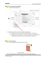
Страница 61: ...rs feature a standard Accu Aligning System AAS II to guarantee precise contour cutting quality by detecting the registration marks printed around the graphic Notice Avoid any kind of light source hori...

Страница 62: ...a for best cutting result It is not necessary to perform media calibration every time unless the registration marks on the printed media become undetectable in AAS sensing process 5 2 2 AAS Calibratio...

Страница 63: ...have to be created on your graphic designs by cutting software like CorelDraw plug in Hand made marks or drawings won t be reorganized by Mutoh cutting plotters For more details about registration ma...

Страница 64: ...n the Segmental Positioning parameters Cutting sequence Date Block1 Date Block2 Date Block3 Date Block4 3 Multiple Copies The function is used to duplicate images to let you cut quantities of images a...

Страница 65: ...Direction detection steps a Detects the position of the 3rd Registration Mark b Proceeds to the 4th Registration Mark to detect the direction The existing detection procedure will be performed follow...

Страница 66: ...ne and the actual cutting line Enter the AAS Offset under MISC function for the values you just measured then press Enter Test the cutting again AAS II offset X and Y value is defined as following Hor...

Страница 67: ...aphic and contour line TIPS2 Create the contour in a separate layer and assign a different color for it Add registration marks around the graphic Note Before adjusting the AAS II settings please proce...

Страница 68: ...y area Suggested 30mm margin on both left and right sides of media sheet Suggested 50 70 mm margin on top and bottom edge of the media sheet to prevent sheets dropping or any error occurred while medi...

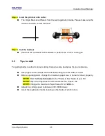
Страница 69: ...etter results of contour cutting there are some tips below for your reference Keep light sources simple and avoid illuminating from the sides of cutter Before operating AAS change the maximum paper si...

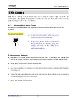
Страница 70: ...ree cloth If necessary with a damp cloth immersed in water or alcohol Dry and wipe any remaining residue off a soft lint free cloth Wipe all dust and dirt from the tool carriage rails Use a vacuum cle...

Страница 71: ...Rollers 1 If the pinch rollers require a thorough cleaning use a lint free cloth or cotton swab to wipe away the accumulated dust from the rubber portion of the pinch rollers To prevent the pinch roll...

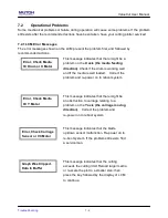
Страница 72: ...ower connector properly Does the power LED still illuminate Solutions If the LCM is able to display the message the cutting plotter should be in a normal condition Switch off the cutting plotter and t...

Страница 73: ...rum is working well and if the media is well loaded Correct the problem and re power on to reboot system Error Check Media Or Y Motor This message indicates that there might be an obstruction to carri...

Страница 74: ...to release grip Press DISABLE Note Never press the top release grip the release grip is fully pressed when a clip sound is heard and pull the bottom release grip at the same time as the pictures show...

Страница 75: ...edia is correctly loaded refer to the alignment ruler 4 The media lifts Step 1 Stop the operation Step 2 Move the pinch rollers to the side Step 3 Pull the lever up Step 4 Reload the sheet and ensure...

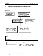
Страница 76: ...tly Refer to Chapter 2 Connecting your cutting plotter Yes No Try the communication between your cutting plotter and computer If it still does not work have your cutting plotter serviced Refer to the...

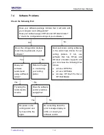
Страница 77: ...d using a different cable Does the software vendor provide a sample file Most well known cutting softwares in the world have drivers for our cutting plotters If not use software that has HP GL and HP...

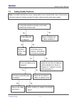
Страница 78: ...an optimum blade force Refer to Chapter 4 3 Cutting Force and Offset Adjustment Is the tool offset set up properly Yes No Adjust the tool offset to obtain an optimum value Is there any dirt adhered to...

Страница 79: ...thing Yes Configurable Origin Yes Test Cut capability Yes Tangential Yes Repeat Yes Copy Yes Pouncing Yes Control Panel LCD 20 digits x 2 lines 14 Keys 1 Power LED Power Supply AC 100 240V 50 60 Hz au...

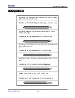
Страница 80: ...and stencil sharp edge The blade is 60 with Green Cap 0 50 mm blade offset For cutting thin sandblast mask and stencil with friction feed or sprocket feed machine The blade is 60 with Blue Cap 0 25 m...

Страница 81: ...g to the reference point OFFSET is the distance that the blade tip is displaced from the centerline of the blade Protrusion Length of the Blade Length of protrusion t1 t 2 2 but for your convenience y...

Страница 82: ...C CBBK1 Cutting Blade Black Cap 42 0 175 1pcs box VC CBYE5 Cutting Blade Yellow Cap 25 0 25 5pcs box PSGB BK Pressurized Ballpoint Pen VC CMAT Cutting Pad W6mm L10m VC PT Pouncing Tool assembly Diamet...

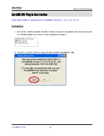
Страница 83: ...RAW Version 11 12 13 14 15 16 Installation 1 Check the AAS CorelDraw Installer folder in ValueCut Installation CD and double click the AASIIInstaller exe file to run the installation program 2 Press t...

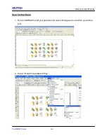
Страница 84: ...ValueCut User Manual CorelDRAW Plug In A 4 User Instructions 1 Run CorelDRAW to edit your graphics and select all images at once when you wish to plot 2 Select Tools Visual Basic Play...

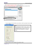
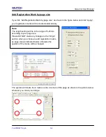
Страница 85: ...3 Click on Apply and select whether you would like to add the registration marks by page size or by object 4 Now you can print out the image file with registration marks Note Note Add Registration Ma...

Страница 86: ...eated automatically The system will create the 4 marks on the 4 corners of the page as shown in the picture below wherever you move your image Note The length setting will be in the range of 5 25mm ac...

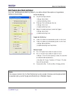
Страница 87: ...X Step The distance of intermediate position on the X axis Y Step The distance of intermediate position on the Y axis Range 200mm 600mm Optimized Setting Less than 500mm Multiple Copies No of X Copies...

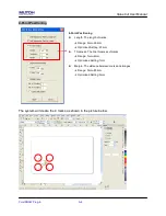
Страница 88: ...e the 4 marks as shown in the picture below 4 Point Positioning Length The length of marks Range 5mm 50mm Optimized Setting 25mm Thickness The line thickness of marks Range 1mm 2mm Optimized Setting 1...

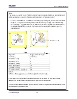
Страница 89: ...The smaller the size is the smaller the distance between the object and the registration marks is see the figures below Page size unit inch Suggested mark length unit mm A6 4 13 5 83 5 A5 5 83 8 27 8...

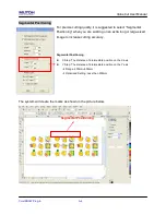
Страница 90: ...working on an extra long or large sized image to increase cutting accuracy Segmental Positioning X Step The distance of intermediate position on the X axis Y Step The distance of intermediate positio...

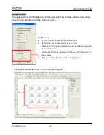
Страница 91: ...uracy Multiple Copies No of X Copies The numbers of copies on X axis No of Y Copies The numbers of copies on Y axis Range 1 50 The more copies you make the more time is needed for data transmission Nu...

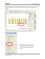
Страница 92: ...e Copies when the object to be copied is of large size with the length or width over 200mm to increase the accuracy of registration mark detection Segmental Positioning Please make sure you are happy...

Страница 93: ...ition the paper with registration marks printed by your printer on the cutter Step 2 Select Files Print Please note that if you use CorelDraw X5 you must follow the steps below Click the color page an...

Страница 94: ...relDRAW Plug In A 4 Step 2 Go to the Layout page and select Bottom left corner at Reposition images to Step 3 Click Print You can also add a Hot Icon for the AAS II Plug in Step 1 Select Tools Customi...

Страница 95: ...oose _CorelDraw_AASII Module _AASII and drag it to the commands bar Step 3 If you want to have a different icon select Tools Customization Commands Appearance to import a graphics for use as the icon...

Страница 96: ...CS4 CS5 CS6 Installation 1 Check the AAS Illustrator Installer folder in ValueCut Installation CD and double click the AASIIInstaller exe file to run the installation program 2 Press the Install butto...

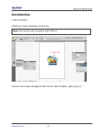
Страница 97: ...Plug In A 5 User Instructions 1 Open Illustrator 2 Edit your image and create a contour line 3 Click on the image and apply the AAS function File Scripts _AASII_Plug_In Contour line Note You must hav...

Страница 98: ...alueCut User Manual Illustrator Plug In A 5 4 Select the registration marks needed 5 Three types of registration marks are introduced here 4 Point Positioning Segmental Positioning and Multiple Copies...

Страница 99: ...registration marks the 4 Point Position mark is used as an illustration in the following steps Note The values entered in the 4 Point Positioning section length thickness and margin will still be appl...

Страница 100: ...anual Illustrator Plug In A 5 7 Click on the blank area on the page and then click Document Setup 8 Hit Edit Artboards Note Keep all Bleed settings as zero when performing segmental cutting to ensure...

Страница 101: ...lueCut User Manual Illustrator Plug In A 5 9 Click on Presets Fit Artboard to Artwork bounds 10 Please move your mouse to the tool bar on the left when step 10 is finished and then click Selection Too...

Страница 102: ...you back to the edit mode 12 Print out the file with the contour line and the registration marks 13 Place the printed file on the cutter lower the pinch rollers and then position the carriage at the o...

Страница 103: ...ValueCut User Manual Illustrator Plug In A 5 15 Select the cutter model position the object in the bottom left corner and then click Print 16 Your job is now completed...

Страница 104: ...system will create the 4 marks as shown in the picture below 4 Point Positioning Length The length of marks Range 5mm 50mm Optimized Setting 25mm Thickness The line thickness of marks Range 1mm 2mm O...

Страница 105: ...The smaller the size is the smaller the distance between the object and the registration marks is see the figures below Page size unit inch Suggested mark length unit mm A6 4 13 5 83 5 A5 5 83 8 27 8...

Страница 106: ...e working on an extra long or large sized image to increase cutting accuracy Segmental Positioning X Step The distance of intermediate position on the X axis Y Step The distance of intermediate positi...

Страница 107: ...es The numbers of copies on X axis No of Y Copies The numbers of copies on Y axis Range 1 50 The more copies you make the more time is needed for data transmission Numbers of X Copies Numbers of Y Cop...

Страница 108: ...ValueCut User Manual Illustrator Plug In A 5...

Отзывы: