4. SETPOINT PROGRAMMING
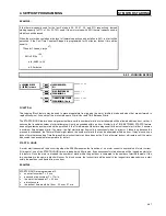
S6 CURRENT ELEMENTS
4-41
4.7.2
OVERLOAD ALARM
y
#
29(5/2$'
#
$/$50
y
#
>(17(5@
#
IRU
#
PRUH
Õ
Õ
Õ
Õ
ENTER
ENTER
ENTER
ENTER
ESCAPE
ESCAPE
ESCAPE
ESCAPE
Ö
Ö
Ö
Ö
29(5/2$'
$/$50
=#
2II
B1>75*ð?VVäð<QdSXUTäðE^\QdSXUT
Û
Û
Û
Û
ESCAPE
ESCAPE
ESCAPE
ESCAPE
MESSAGE
MESSAGE
MESSAGE
MESSAGE
Ú
Ú
Ú
Ú
$66,*1
#
$/$50
#
5(/$<6
=
$ODUP
B1>75*ð1\Qb]äð1\Qb]ðêð1ehY\YQbi"äð1\Qb]ðêð1eh"ðêð1eh#äð1\Qb]ðêð1ehY\YQbi#äð1ehY\YQbi"äð
ðð1eh"ðêð1eh#äð1ehY\YQbi#
Û
Û
Û
Û
ESCAPE
ESCAPE
ESCAPE
ESCAPE
MESSAGE
MESSAGE
MESSAGE
MESSAGE
×
×
×
×
29(5/2$'
#
$/$50
'(/$<
=###314#
V
B1>75*ð â!ðãð&
CD5@*ð â!
Û
Û
Û
Û
ESCAPE
ESCAPE
ESCAPE
ESCAPE
MESSAGE
MESSAGE
MESSAGE
MESSAGE
×
×
×
×
29(5/2$'
#
$/$50
(9(176
=#
2II
B1>75*ð?^äð?VV
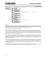
FUNCTION:
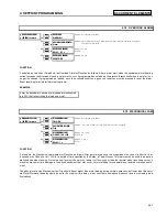
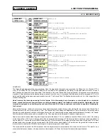
If enabled as Latched or Unlatched, the Overload Alarm will function as follows: After a motor start, when the equivalent motor heating
current exceeds the Overload Pickup, an alarm will occur. If programmed as unlatched, the alarm will reset itself when the motor is no
longer in overload. If programmed as latched, once the overload condition is gone, the reset key must be pressed to reset the alarm.
Event recording for all alarm features is optional.
EXAMPLE:
It may be desirable to have an unlatched alarm connected
to a PLC that is controlling the load on a motor.
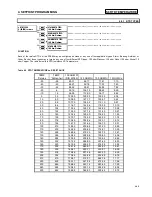
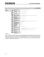
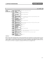
4.7.3
MECHANICAL JAM
y
#
0(&+$1,&$/
#
-$0
y
#
>(17(5@
#
IRU
#
PRUH
Õ
Õ
Õ
Õ
ENTER
ENTER
ENTER
ENTER
ESCAPE
ESCAPE
ESCAPE
ESCAPE
Ö
Ö
Ö
Ö
0(&+$1,&$/
#
-$0
75,3
=#
2II
B1>75*ð?VVäð<QdSXUTäðE^\QdSXUT
Û
Û
Û
Û
ESCAPE
ESCAPE
ESCAPE
ESCAPE
MESSAGE
MESSAGE
MESSAGE
MESSAGE
Ú
Ú
Ú
Ú
$66,*1
#
75,3
#
5(/$<6
=
7ULS
B1>75*ðDbY`äðDbY`ðêð1ehY\YQbið"äðDbY`ðêð1eh"ðêð1eh#äðDbY`ðêð1ehY\YQbi#
Û
Û
Û
Û
ESCAPE
ESCAPE
ESCAPE
ESCAPE
MESSAGE
MESSAGE
MESSAGE
MESSAGE
Ú
Ú
Ú
Ú
0(&+$1,&$/
#
-$0
3,&.83
=#4183#
[
#
)/$
B1>75*ð!â !ðãð#â
CD5@*ð â !
Û
Û
Û
Û
ESCAPE
ESCAPE
ESCAPE
ESCAPE
MESSAGE
MESSAGE
MESSAGE
MESSAGE
×
×
×
×
0(&+$1,&$/
#
-$0
'(/$<
#=#4#
V
B1>75*ð!ðã#
CD5@*ð!
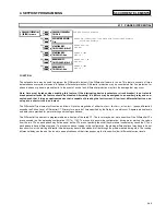
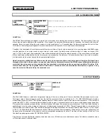
FUNCTION:
If turned On, the Mechanical Jam element will function as follows: After a motor start, once the magnitude of any one of either Ia, Ib, or
Ic exceeds the Pickup Level × FLA for a period of time specified by the Delay, a Trip will occur. This feature may be used to indicate a
stall condition when running. Not only does it protect the motor by taking it off-line quicker than the thermal model (overload curve), it
may also prevent or limit damage to the driven equipment that may occur if motor starting torque persists on jammed or broken equip-
ment.
The pickup level for the Mechanical Jam Trip should be set higher than motor loading during normal operations, but lower than the motor
stall level. Normally the delay would be set to the minimum time delay, or set such that no nuisance trips occur due to momentary load
fluctuations.
Содержание SR469
Страница 7: ......
Страница 19: ...2 INSTALLATION MECHANICAL 2 5 2 1 5 TERMINAL LOCATIONS Figure 2 11 TERMINAL LAYOUT...
Страница 21: ...2 INSTALLATION ELECTRICAL 2 7 Figure 2 12 TYPICAL WIRING DIAGRAM...
Страница 32: ...ELECTRICAL 2 INSTALLATION 2 18 2 2 14 TYPICAL 2 SPEED MOTOR WIRING...
Страница 39: ...OVERVIEW 3 SR469 OPERATION 3 6 yy SETPOINTS yy S1 SR469 SETUP...
Страница 104: ...4 SETPOINT PROGRAMMING S11 MONITORING 4 65 Figure 4 24 TRIP COIL SUPERVISION...
Страница 113: ...S12 ANALOG I O 4 SETPOINT PROGRAMMING 4 74...
Страница 244: ...8 469PC PROGRAM WAVEFORM CAPTURE 8 13 Figure 8 11 WAVEFORM CAPTURE...


