


S5 THERMAL MODEL
4. SETPOINT PROGRAMMING
4-32
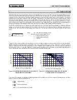
VOLTAGE DEPENDENT OVERLOAD CURVE
If the motor is called upon to drive a high inertia load, it is quite possible and acceptable that the acceleration time exceeds the safe
stall time. (Bearing in mind that a locked rotor condition is quite different than an acceleration condition). In this instance, each distinct
portion of the thermal limit curve must be known and protection must be coordinated against that curve. The relay that is protecting the
motor must be able to distinguish between a locked rotor condition, an accelerating condition and a running condition. The SR469 Volt-
age Dependent Overload Curve feature is tailored to protect these types of motors. Voltage is monitored constantly during motor start-
ing and the acceleration thermal limit curve is adjusted accordingly.
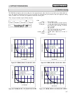
The Voltage Dependent Overload Curve, is comprised of the three characteristic shapes of thermal limit curves as determined by the
stall or locked rotor condition, acceleration, and running overload. The curve is constructed by entering a custom curve shape for the
running overload protection curve. Next, a point must be entered for the acceleration protection curve at the point of intersection with the
custom curve, based on the minimum allowable starting voltage as defined by the minimum allowable line voltage. Locked Rotor Current
and safe stall time must also be entered for that voltage. A second point of intersection must be entered for 100% line voltage. Once
again, the locked rotor current and the safe stall time must be entered, this time for 100% line voltage. The protection curve that is cre-
ated from the safe stall time and intersection point will be dynamic based on the measured line voltage between the minimum allowable
line voltage and the 100% line voltage. This method of protection inherently accounts for the change in motor speed as an impedance
relay would. The change in impedance is reflected by motor terminal voltage and line current. For any given speed at any given line
voltage, there is only one value of line current.
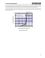
EXAMPLE: To illustrate the Voltage Dependent Overload Curve feature, the thermal limits of Figure 4-10 will be used.
Figure 4-10 THERMAL LIMITS FOR HIGH INERTIAL LOAD
Содержание SR469
Страница 7: ......
Страница 19: ...2 INSTALLATION MECHANICAL 2 5 2 1 5 TERMINAL LOCATIONS Figure 2 11 TERMINAL LAYOUT...
Страница 21: ...2 INSTALLATION ELECTRICAL 2 7 Figure 2 12 TYPICAL WIRING DIAGRAM...
Страница 32: ...ELECTRICAL 2 INSTALLATION 2 18 2 2 14 TYPICAL 2 SPEED MOTOR WIRING...
Страница 39: ...OVERVIEW 3 SR469 OPERATION 3 6 yy SETPOINTS yy S1 SR469 SETUP...
Страница 104: ...4 SETPOINT PROGRAMMING S11 MONITORING 4 65 Figure 4 24 TRIP COIL SUPERVISION...
Страница 113: ...S12 ANALOG I O 4 SETPOINT PROGRAMMING 4 74...
Страница 244: ...8 469PC PROGRAM WAVEFORM CAPTURE 8 13 Figure 8 11 WAVEFORM CAPTURE...


