


4. SETPOINT PROGRAMMING
S6 CURRENT ELEMENTS
4-43
4.7.5
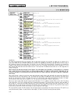
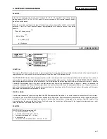
CURRENT UNBALANCE
y
#
&855(17
81%$/$1&(
y
#
>(17(5@
#
IRU
#
PRUH
Õ
Õ
Õ
Õ
ENTER
ENTER
ENTER
ENTER
ESCAPE
ESCAPE
ESCAPE
ESCAPE
Ö
Ö
Ö
Ö
&855(17
#
81%$/$1&(
$/$50
=#
2II
B1>75*ð?VVäð<QdSXUTäðE^\QdSXUT
Û
Û
Û
Û
ESCAPE
ESCAPE
ESCAPE
ESCAPE
MESSAGE
MESSAGE
MESSAGE
MESSAGE
Ú
Ú
Ú
Ú
$66,*1
#
$/$50
#
5(/$<6
=
$ODUP
B1>75*ð1\Qb]äð1\Qb]ðêð1ehY\YQbi"äð1\Qb]ðêð1eh"ðêð1eh#äð1\Qb]ðêð1ehY\YQbi#äð1ehY\YQbi"ä
ðð1eh"ðêð1eh#äð1ehY\YQbi#
Û
Û
Û
Û
ESCAPE
ESCAPE
ESCAPE
ESCAPE
MESSAGE
MESSAGE
MESSAGE
MESSAGE
Ú
Ú
Ú
Ú
&855(17
#
81%$/$1&(
$/$50
#
3,&.83
=#48#(
B1>75*ð$ðãð$
CD5@*ð!
Û
Û
Û
Û
ESCAPE
ESCAPE
ESCAPE
ESCAPE
MESSAGE
MESSAGE
MESSAGE
MESSAGE
×
×
×
×
&855(17
#
81%$/$1&(
$/$50
##
'(/$<
=#4#
V
B1>75*ð!ðãð&
CD5@*ð!
Û
Û
Û
Û
ESCAPE
ESCAPE
ESCAPE
ESCAPE
MESSAGE
MESSAGE
MESSAGE
MESSAGE
Ú
Ú
Ú
Ú
&855(17
#
81%$/$1&(
$/$50
#
(9(176
=#
2II
B1>75*ð?^äð?VV
Û
Û
Û
Û
ESCAPE
ESCAPE
ESCAPE
ESCAPE
MESSAGE
MESSAGE
MESSAGE
MESSAGE
Ú
Ú
Ú
Ú
&855(17
#
81%$/$1&(
75,3
=#
2II
B1>75*ð?VVäð<QdSXUTäðE^\QdSXUT
Û
Û
Û
Û
ESCAPE
ESCAPE
ESCAPE
ESCAPE
MESSAGE
MESSAGE
MESSAGE
MESSAGE
Ú
Ú
Ú
Ú
$66,*1
#
75,3
#
5(/$<6
=
7ULS
B1>75*ðDbY`äðDbY`ðêð1ehY\YQbið"äðDbY`ðêð1eh"ðêð1eh#äðDbY`ðêð1ehY\YQbi#
Û
Û
Û
Û
ESCAPE
ESCAPE
ESCAPE
ESCAPE
MESSAGE
MESSAGE
MESSAGE
MESSAGE
Ú
Ú
Ú
Ú
&855(17
#
81%$/$1&(
75,3
#
3,&.83
=#53#(
B1>75*ð$ðãð$
CD5@*ð!
Û
Û
Û
Û
ESCAPE
ESCAPE
ESCAPE
ESCAPE
MESSAGE
MESSAGE
MESSAGE
MESSAGE
×
×
×
×
&855(17
#
81%$/$1&(
75,3
#
'(/$<
=#4#
V
B1>75*ð!ðãð&
CD5@*ð!
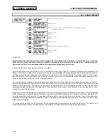
FUNCTION:
SR469 unbalance is defined as the ratio of negative sequence current to positive sequence current, I
2
/I
1
, if the motor is operating at a
load (Iavg) greater than FLA. If the motor Iavg is less than FLA, unbalance is defined as I
2
/I
1
× Iavg/FLA. This derating is necessary to
prevent nuisance alarms when a motor is lightly loaded. If enabled, once the magnitude of unbalance exceeds the Pickup Level for a
period of time specified by the Delay, a trip and/or alarm will occur. If the unbalance level exceeds 40%, or when Iavg > 25% FLA and
current in any one phase is zero, the motor will be considered single phasing and a trip will occur within 2 seconds. Single Phasing pro-
tection is disabled if the Unbalance Trip feature is turned Off.
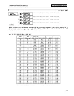
When setting the unbalance pickup level, it should be noted that a 1% voltage unbalance typically translates into a 6 % current unbal-
ance. Therefore, in order to prevent nuisance trips or alarms, the pickup level should not be set too low. Also, since short term unbal-
ances are common, a reasonable delay should be set to avoid nuisance trips or alarms. It is recommended that the Unbalance Thermal
Bias feature be used to bias the Thermal Model to account for motor heating that may be caused by cyclic short term unbalances.
NOTE: Unusually high unbalance levels may be caused by incorrect phase CT wiring.
EXAMPLE:
Fluctuations of current unbalance levels are typically caused
by the supply voltage; it may be desirable to have a latched
alarm to capture any such fluctuations that go beyond the
Unbalance Alarm parameters. Also, a trip is recommended.
If the supply voltage is normally unbalanced up to 2 %, the
current unbalance a typical motor would see is 2 × 6 = 12%,
set the alarm pickup at 15 and the trip pickup at 20 to pre-
vent nuisance tripping. 5 or 10 seconds is a reasonable de-
lay.
Содержание SR469
Страница 7: ......
Страница 19: ...2 INSTALLATION MECHANICAL 2 5 2 1 5 TERMINAL LOCATIONS Figure 2 11 TERMINAL LAYOUT...
Страница 21: ...2 INSTALLATION ELECTRICAL 2 7 Figure 2 12 TYPICAL WIRING DIAGRAM...
Страница 32: ...ELECTRICAL 2 INSTALLATION 2 18 2 2 14 TYPICAL 2 SPEED MOTOR WIRING...
Страница 39: ...OVERVIEW 3 SR469 OPERATION 3 6 yy SETPOINTS yy S1 SR469 SETUP...
Страница 104: ...4 SETPOINT PROGRAMMING S11 MONITORING 4 65 Figure 4 24 TRIP COIL SUPERVISION...
Страница 113: ...S12 ANALOG I O 4 SETPOINT PROGRAMMING 4 74...
Страница 244: ...8 469PC PROGRAM WAVEFORM CAPTURE 8 13 Figure 8 11 WAVEFORM CAPTURE...


