4. SETPOINT PROGRAMMING
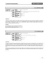
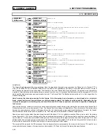
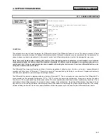
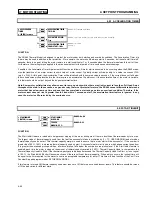
S5 THERMAL MODEL
4-33
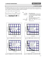
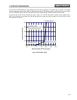
1.
Construct a custom curve for the running overload thermal limit. If the curve does not extend to the acceleration thermal limits, extend
it such that the curve intersects the acceleration thermal limit curves. (see Figure 4-11)
2.
Enter the per unit current value for the acceleration overload curve intersect with the custom curve for 80% line voltage. Also enter the
per unit current and safe stall protection time for 80% line voltage. (see Figure 4-12)
3.
Enter the per unit current value for the acceleration overload curve intersect with the custom curve for 100% line voltage. Also enter
the per unit current and safe stall protection time for 100% line voltage. (see Figure 4-12)
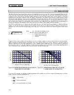
Figure 4-11 VOLTAGE DEPENDENT OVERLOAD
(CUSTOM CURVE)
Figure 4-12 VOLTAGE DEPENDENT OVERLOAD
(ACCELERATION CURVES)
Содержание SR469
Страница 7: ......
Страница 19: ...2 INSTALLATION MECHANICAL 2 5 2 1 5 TERMINAL LOCATIONS Figure 2 11 TERMINAL LAYOUT...
Страница 21: ...2 INSTALLATION ELECTRICAL 2 7 Figure 2 12 TYPICAL WIRING DIAGRAM...
Страница 32: ...ELECTRICAL 2 INSTALLATION 2 18 2 2 14 TYPICAL 2 SPEED MOTOR WIRING...
Страница 39: ...OVERVIEW 3 SR469 OPERATION 3 6 yy SETPOINTS yy S1 SR469 SETUP...
Страница 104: ...4 SETPOINT PROGRAMMING S11 MONITORING 4 65 Figure 4 24 TRIP COIL SUPERVISION...
Страница 113: ...S12 ANALOG I O 4 SETPOINT PROGRAMMING 4 74...
Страница 244: ...8 469PC PROGRAM WAVEFORM CAPTURE 8 13 Figure 8 11 WAVEFORM CAPTURE...


