MVME197LE Functional Description
MVME197LE/D2
4-9
4
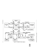
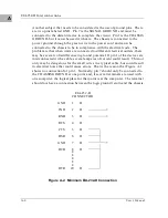
other external sources (PALINT and IRQ). The BusSwitch may also generate
the non-maskable interrupt (NMI) signal to the MPU from the ABORT push-
button switch. Refer to the BusSwitch, PCCchip2, and VMEchip2 chapters in the
MVME197LE, MVME197DP, and MVME197SP Single Board Computers
Programmer’s Reference Guide for more detailed information.
Содержание MVME197LE
Страница 1: ...MVME197LE Single Board Computer User s Manual MVME197LE D2 ...
Страница 12: ...xii ...
Страница 14: ...xiv ...
Страница 22: ...Hardware Preparation and Installation 2 2 User s Manual 2 ...
Страница 30: ...Hardware Preparation and Installation 2 10 User s Manual 2 ...
Страница 37: ...Memory Maps MVME197LE D2 3 7 3 ...
Страница 40: ...Operating Instructions 3 10 User s Manual 3 ...
Страница 42: ...Operating Instructions 3 12 User s Manual 3 ...
Страница 44: ...Operating Instructions 3 14 User s Manual 3 ...
Страница 46: ...Operating Instructions 3 16 User s Manual 3 ...
Страница 48: ...Operating Instructions 3 18 User s Manual 3 ...
Страница 60: ...Functional Description 4 2 User s Manual 4 ...
Страница 68: ...Functional Description 4 10 User s Manual 4 ...
Страница 78: ...Index IN 4 User s Manual I N D E X ...

