Operating Instructions
3-2
User’s Manual
3
by a control bit in the LCSR. SYSRESET* remains asserted for at least 200 msec,
as required by the VMEbus specification.
Similarly, the VMEchip2 provides an input signal and a control bit to initiate
a local reset operation. By setting a control bit, software can maintain a board
in a reset state, disabling a faulty board from participating in normal system
operation.
The local reset driver is enabled even when the VMEchip2 is not the system
controller. A local reset may be generated by the RESET switch, a power up
reset, a watchdog timeout, a VMEbus SYSRESET*, or a control bit in the GCSR.
Front Panel Indicators (DS1-DS6)
The six LEDs on the MVME197LE front panel are: FAIL, SCON, RUN, LAN,
VME, and SCSI.
1.
The yellow FAIL LED (DS1) is lit when the BRDFAIL signal line is active.
2.
The green SCON LED (DS2) is lit when the VMEchip2 is the VMEbus
system controller.
3.
The green RUN LED (DS3) is lit when the MC88110 bus MC* pin is low.
4.
The green LAN LED (DS4) lights when the LAN chip is the local
peripheral bus master.
5.
The green VME LED (DS5) lights when the board is using the VMEbus or
when the board is accessed by the VMEbus.
6.
The green SCSI LED (DS6) lights when the SCSI chip is the local peripheral
bus master.
Memory Maps
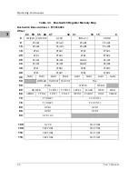
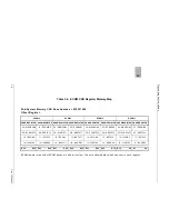
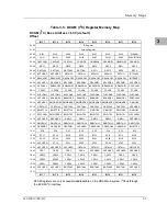
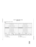
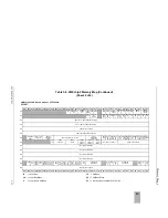
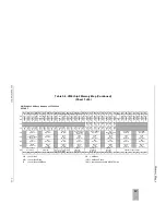
There are three points of view for the memory maps: 1) the mapping of all
resources as viewed by the Processor Bus (MC88110 bus), 2) the mapping of
onboard/off-board resources as viewed from the Local Peripheral Bus
(MC68040 compatible bus), and 3) the mapping of onboard resources as
viewed by VMEbus Masters (VMEbus memory map).
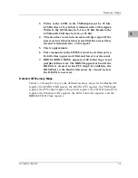
Processor Bus Memory Map
Care should be taken, since all three maps are programmable. It is
recommended that direct mapping from the Processor Bus to the Local
Peripheral Bus be used.
Содержание MVME197LE
Страница 1: ...MVME197LE Single Board Computer User s Manual MVME197LE D2 ...
Страница 12: ...xii ...
Страница 14: ...xiv ...
Страница 22: ...Hardware Preparation and Installation 2 2 User s Manual 2 ...
Страница 30: ...Hardware Preparation and Installation 2 10 User s Manual 2 ...
Страница 37: ...Memory Maps MVME197LE D2 3 7 3 ...
Страница 40: ...Operating Instructions 3 10 User s Manual 3 ...
Страница 42: ...Operating Instructions 3 12 User s Manual 3 ...
Страница 44: ...Operating Instructions 3 14 User s Manual 3 ...
Страница 46: ...Operating Instructions 3 16 User s Manual 3 ...
Страница 48: ...Operating Instructions 3 18 User s Manual 3 ...
Страница 60: ...Functional Description 4 2 User s Manual 4 ...
Страница 68: ...Functional Description 4 10 User s Manual 4 ...
Страница 78: ...Index IN 4 User s Manual I N D E X ...

