


Chapter 2: Network Setup
IP Addressing Plan
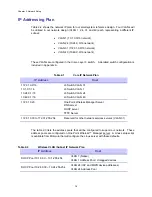
Table 2-2 shows the network IP plan for our small system reference design. Four VLANs will
be utilized in our network design (VLAN 1, 24, 31, and 49) each representing a different IP
subnet:
•
VLAN 1 (10.1.0.0/16 network)
•
VLAN 24 (10.24.0.0/16 network)
•
VLAN 31 (172.31.0.0/16 network)
•
VLAN 49 (10.49.0.0/16 network)
These VLANs are configured in the Cisco Layer 3 switch. A detailed switch configuration is
included in Appendix A.
Table 2-1
Core IP Network Plan
IP Address
Host
172.31.0.2/16
10.1.0.1/16
10.24.0.1/16
10.49.0.1/16
L3 Switch VLAN 31
L3 Switch VLAN 1
L3 Switch VLAN 24
L3 Switch VLAN 49
172.31.0.20
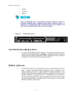
One Point Wireless Manager Server
DNS server
DHCP server
TFTP Server
172.31.0.30 to 172.31.255.254
Reserved for other network services servers (VLAN 31)
The table 2-3 lists the address pools that will be configured to support our network. These
address pools are configured on One Point Wireless™ Manager server. A Linux setup script
is available from Motorola that will configure the Linux server with these defaults.
Table 2-2
Wireless VLAN /Subnet IP Network Plan
IP Address
Host
DHCP Pool 10.1.0.30 – 10.1.255.254
VLAN 1 (Native)
VLAN 1 Address Pool / Untagged devices
DHCP Pool 10.24.0.30 – 10.24.255.254
VLAN 24 (IAP and MWR device addresses)
VLAN 24 Address Pool
2-8
Содержание 2.1
Страница 2: ...This page intentionally left blank ii ...
Страница 4: ...This page intentionally left blank iv ...
Страница 10: ...This page intentionally left blank x ...
Страница 12: ...This page intentionally left blank xii ...
Страница 14: ...This page intentionally left blank xiv ...
Страница 59: ...Chapter 3 MOTOMESH Duo Hardware This page intentionally left blank 3 12 ...
Страница 86: ...Chapter 5 Customer Information This page intentionally left blank 5 7 ...
Страница 123: ......
Страница 131: ...Appendix A Figure 9 39 General Settings Tab in the Web User Interface 9 30 ...


