The Interface Solution Experts
9
FDY
PC-Programmable Frequency
Transmitter and Display
FDY
COM
+PS
0
+ –
–PS
0
6027.8
H Z
–
+
–
+
POWER
SOURCE
12-42Vdc
MULTIMETER
4-20mA
–
+
CALIBRATED
DC INPUT
SIMULATOR
FDY COMMUNICATION CABLE
803-040-26 FOR NON-ISOLATED
803-039-26 FOR ISOLATED
or Optional USB Cable 208-836-00
CALIBRATED
AC INPUT
SIMULATOR
OR
250 ohms
FREQ.
COUNTER
FREQ.
COUNTER
Device
Variable, accurate to ±0.005% of reading
12-42Vdc
250 ohms, ±0.01%
Accurate to ±0.025% of reading
Microsoft Windows based PC;
16Mb free RAM; 20MB free disk space on hard
drive
Microsoft Windows XP, Vista or 7
1 (one) serial port or one available USB port
(with optional USB cable)
Isolated cable P/N: 803-039-26
Non-isolated cable P/N: 803-040-26
or optional USB cable P/N: 208-836-00
Version 1.0 or greater,
part number: 750-75E05-01
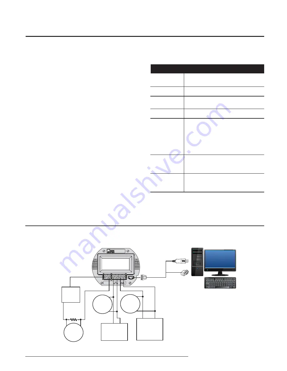
Figure 6.
Connecting the FDY to the PC
Table 9.
Assembling the Necessary Equipment
Device
Frequency Input
Simulator
Power Supply
Precision Load
Resistor
Multimeter
Personal
Computer
Communications
Cable
Communications
Software
Programming the FDY
All operating parameters of the FDY are set using
a PC, a serial communication cable and Moore
Industries’ Intelligent PC Confi guration software. When
the PC Confi guration program is loaded and running,
most of the parameters for the connected transmitter
are shown on a single screen. This makes it easy to
determine which aspects of transmitter operation need
to be changed to suit the application requirements.
Once the software settings are made, they are
downloaded to the transmitter in the form of a
confi guration fi le and stored in the non-volatile unit
memory. You can choose to save a backup copy of the
fi le on your PC hard drive or external media.
Program the FDY by connecting the FDY to the PC,
setting the appropriate parameters in the PC program,
and downloading the confi guration.
Connecting the FDY to the PC
The fi rst step in confi guring the FDY is connecting
the transmitter to the PC program and attaching the
appropriate input devices. Connect the FDY as shown
in Figure 6 below; refer to Table 9 for a description of
required equipment. After the FDY is confi gured, you
can begin programming the basic parameters.


