5-565.1
23
oPtions
Outdoor Enthalpy Changeover Set Point
The outdoor enthalpy changeover set point returns the outdoor
air damper to the minimum position when the enthalpy rises
above its set point. Enthalpy set point scale markings, located
on the enthalpy controller, are A, B, C, and D. See Figure 24.2
for the corresponding control point. The factory installed 620-
ohm jumper placed across terminals S
R
and + is required for
proper operation and should not be removed. Refer to suppliers
literature supplied with the unit for additional information.
(32) damper to damper linkage – (oPt)
Units with fresh and return air dampers include a damper
actuator that controls the fresh air damper. The return air
damper position is controlled by the fresh air damper through
the connecting rod. For adjustment, refer to Damper Linkage
Adjustment.
(
33) return air damper – (oPt)
When a return air damper is supplied with the unit, the damper
is factory installed in the blower section. The return air damper is
used as an air balancing damper so low leak, Class III leakage
resistance (less than 40 CFM/ft2 at 1" W.C.) dampers with self-
compensating stainless steel side seals and santoprene blade
seals are used.
(34) Proportional temperature controller sensor – (oPt)
A proportional temperature controller sensor is provided with Air
Control options GF, GG, GH, GK, GM, or GN (Digits 20 & 21)
and factory installed in the blower section. The sensor provides
the mixed air temperature signal to the A350P Proportional
Temperature Controller which is mounted in the electrical
section.
(
35) motor and Blower vibration isolation – (oPt)
The motor vibration isolation is factory installed in the blower
section below the blower support bracket. The four (4) 13/32"
neoprene vibration mount grommet provides isolation of the
blower housing and motor from the blower support channels.
The blower vibration isolation is factory installed in the
blower section between blower discharge and the blower
duct connection. The blower duct connection is not rigidly
mechanically fastened and the 1/4'' thick gasketing around the
duct transition provides vibration isolation.
(36) Blower support – (std)
The blower supports are factory installed in the blower section.
The blower supports are used to rigidly support the weight of the
blower and motor during operation and shipping.
(37) convenience outlet – (oPt)
The convenience outlet is factory installed in the blower section
for providing power for 115V service equipment (trouble light,
power tools, etc.). The 115V ground fault circuit interrupter
(GFCI) is rated for 15 amps and includes test and reset
switches. A separate field supplied 115V/1Ph power supply must
be routed through the electrical section wall into the back of the
convenience outlet junction box.
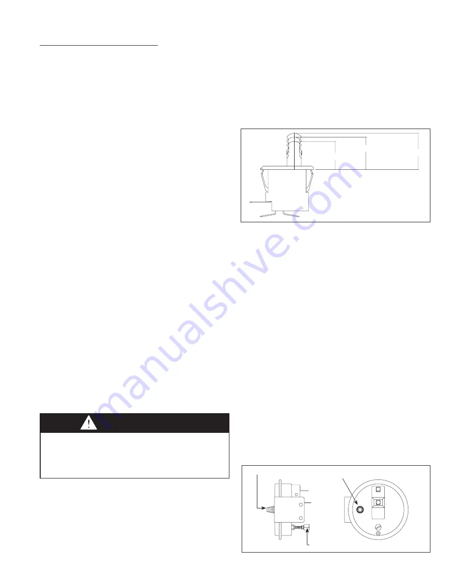
(38) Blower door switch – (oPt)
The blower door switch is factory installed inside the blower
WARNING
Do not perform service on the convenience outlet without
disconnecting its power supply. The convenience outlet
power supply is separate from main power supply to the
unit. When the main disconnect switch is de-energized,
the convenience outlet power supply remains energized.
section door on the access side of the unit. When the blower
section door is removed, the momentary switch is released and
interrupts power to the low voltage circuit. For single phase
units 1-1/2 Hp and less, the door switch de-energizes a relay
that controls blower motor operation. For three phase units
and single phase units 2 Hp and greater, the door switch de-
energizes the motor starter that controls blower motor operation.
For servicing, the switch is equipped with an override position
that can be manually pulled out to override the switch. See
Figure 23.1
(
39) dirty filter switch – (oPt)
The dirty filter pressure switch is factory installed in the electrical
section. The dirty filter pressure switch monitors the pressure
differential between the two sides of the filters. When the filters
become dirty, the differential pressure increases and trips
the pressure switch which energizes a light on the remote
monitoring panel. The pressure differential switch must be field
set because setting the switch requires the blower to be in
operation and the ductwork to be installed.
setting the dirty filter switch
The range of the dirty filter pressure switch is adjustable
between 0.17" to 5.0" W.C.
1. Ensure that the unit filters are clean. Clean or replace if
necessary.
2. Connect the leads of a continuity tester to the NO and C
terminals of the dirty filter pressure switch. See Figure 23.2
3. Set the thermostat so that there is a call for heat. This should
fire the burner and the blower should start.
4. Turn the set screw of the pressure switch clockwise until
it stops. This will set the pressure at 5.0" W.C. and the
continuity tester should be sensing an open circuit.
5. Begin turning the screw counterclockwise until the continuity
tester senses a closed circuit. This determines the base
pressure of the system.
6. Turn the screw clockwise until the continuity tester senses an
open circuit and then one additional full turn (This is approx-
imately 0.25" W.C.) This will allow for the increase in static
pressure due to dirty filters.
figure 23.1 - Blower door switch with manual override
NO
NC
COM
Operating Point
Rest position
"Cheat Interlock" Point
C
NO
Positive pressure connector
Pressure adjustment set screw
Negative pressure
connector
figure 23.2 - dirty filter Pressure switch and air flow
Proving switch


