92-24161-96-01
SUPERSEDES 92-24161-96-00
INSTALLATION INSTRUCTIONS
FOR UPFLOW/HORIZONTAL & DOWNFLOW INDUCEDDRAFT GAS FURNACES WITH ECM X-13 MOTORS
(-)GPT UPFLOW/HORIZONTAL SERIES(-)GLT DOWNFLOW SERIES
Страница 1: ...92 24161 96 01 SUPERSEDES 92 24161 96 00 INSTALLATION INSTRUCTIONS FOR UPFLOW HORIZONTAL DOWNFLOW INDUCED DRAFT GAS FURNACES WITH ECM X 13 MOTORS GPT UPFLOW HORIZONTAL SERIES GLT DOWNFLOW SERIES...
Страница 2: ...el DC microamp A flame signal hot surface ignition units Correct control voltage Measure and set heat anticipator amperage Air conditioning low voltage wires connected to terminals Y C not with wire n...
Страница 3: ...cause cancer or birth defects such as fiberglass insulation lead in brass and combustion products from natural gas All new equipment shipped for sale in California will have labels stating that the pr...
Страница 4: ...ING THE FURNACE THE RETURN AIR SHALL ALSO BE HANDLED BY DUCT S SEALED TO THE FURNACE CASING AND TERMINATING OUTSIDE THE SPACE CONTAINING THE FURNACE WHEN THIS FURNACE IS INSTALLED IN A RESIDENTIAL GAR...
Страница 5: ...ERS OR BOILERS ALL JOINTS SEAMS AND OPENINGS IN THE EQUIPMENT AND DUCT MUST ALSO BE SEALED TO PREVENT DEPRESSURIZATION OF THE SPACE AND POSSIBLE MIGRATION OF COMBUSTION BYPRODUCTS INCLUDING CARBON MON...
Страница 6: ...nology and venting requirements are changing awareness of local state and federal codes and industry changes is imperative NOTE Always perform a proper heat loss calculation before specifying the furn...
Страница 7: ...OMMENDED THAT AN AUXILIARY DRAIN PAN BE INSTALLED UNDER ALL EVAPORATOR COILS OR UNITS CONTAINING EVAPORATOR COILS THAT ARE LOCATED IN ANY AREA OF A STRUCTURE WHERE DAMAGE TO THE BUILDING OR BUILDING C...
Страница 8: ...IGURE 3 UPFLOW HORIZONTAL DIMENSIONS IMPORTANT This furnace is not approved or recommended for installation on its back with access doors facing upwards REDUCED CLEARANCE IN Model A B C D E F Left Rig...
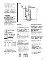
Страница 9: ...15 5 8 23 5 8 0 0 0 1 3 6 140 lbs 15 24 1 2 23 11 32 15 5 8 23 5 8 0 0 0 1 3 6 150 lbs TOP BOTTOM 24 1 2 19 3 4 C A B D LOW VOLTAGE GAS CONNECTION ELECTRIC CONNECTION E S A R A 26 5 8 26 13 16 6 3 16...
Страница 10: ...filter NOTE DO NOT take return air from bathrooms kitchens furnace rooms garages utility or laundry rooms or cold areas IMPORTANT When using outside air design and adjust the system to maintain a ret...
Страница 11: ...indoor coil on the supply air side of the furnace Insure that no air can bypass this coil 3 Connect the supply air plenum to the furnace plenum opening DOWNFLOW UNITS THE DOWNFLOW FURNACE DESIGN IS CE...
Страница 12: ...uded from warranty coverage The following types of installation may require OUTDOOR AIR for combustion due to chemical exposures Commercial buildings Buildings with indoor pools Furnaces installed in...
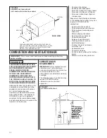
Страница 13: ...ined space any space smaller than shown above as unconfined must have openings into the space which are located in accordance with the requirements set forth in the following subsections A and B Size...
Страница 14: ...ating for all equipment in the enclosure Here are typical duct sizes B Method 2 One permanent opening located within 12 inches of the top of the enclosure shall be permitted where the equipment has cl...
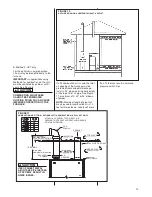
Страница 15: ...at the furnace must be protected from accidental blockage Install a 90 elbow pointing horizontally at the top of inlet air pipe See Figure 11 maximum of 2 45 or 90 elbows allowed NOTE Maximum length o...
Страница 16: ...al Fuel Gas Code ANSI Z223 1 and or the Natural Gas Installation Code CSA B149 1 2 for proper installation practices NOTE Follow combustion air instructions as outlined in this manual Single wall vent...
Страница 17: ...height above the highest connected equipment draft hood or flue collar 3 Must rise 1 4 per foot away from the furnace on horizontal runs and be supported with straps or hangers so it has no sags or d...
Страница 18: ...xhausts so they will operate at maximum speed Do not operate a summer exhaust fan Close fireplace dampers 3 Follow the lighting instructions Place the appliance being inspected into operation Adjust t...
Страница 19: ...e Refer to Table 2 for the recom mended pipe size for natural gas and Table 3 for LP gas pipe sizes IMPORTANT It is permissible to run flexible gas connector inside the unit to a piece of black pipe I...
Страница 20: ...s pressure of 13 w c ELEVATIONS ABOVE 2000 FT REQUIRE THAT THE FURNACE INPUT RATING BE ADJUSTED AND THAT THE SIZE OF THE BURNER ORIFICES BE RE CALCULATED BASED ON ELEVATION AND GAS HEATING VALUE THE B...
Страница 21: ...re at the regulator See Table 3 NOTE Depending on the amount of LP vapor and the outdoor ambient temperature the LP storage tank may require supplemental heat to maintain proper pressure levels Ensure...
Страница 22: ...t ratings apply For high altitudes elevations 8 000 and over and for any necessary major changes in the gas flow rate the orifice spud must be changed TO CHANGE ORIFICE SPUDS 1 Shut off the manual mai...
Страница 23: ...is can be obtained from National Fire Protection Association Batterymarch Park Quincy MA 02269 Canadian Standards Association 178 Rexdale Blvd Etobicoke Toronto Ontario Canada M9W 1R3 WARNING WARNING...
Страница 24: ...DS IMPORTANT ONLY BOTTOM RETURNS CAN BE USED NO MORE THAN TWO FURNACES CAN SHARE THE SAME SUPPLY AND RETURN FURNACES MUST HAVE SAME HEATING AND BLOWER CAPACITY TWINNING FURNACES MUST OPERATE OFF THE S...
Страница 25: ...25 FIGURE 19 UT Electronic Controls 1028 930R2 CONTROL BOARD TWINNING CONNECTION SINGLE STAGE OPERATION a099201...
Страница 26: ...26 FIGURE 20 UTEC 1028 930R2 CONTROL BOARD TWINNING CONNECTION TWO STAGE OPERATION a099301...
Страница 27: ...per thousand ft 47 LP GAS TABLE 7 NOTE Keep any parts removed during LP conversion procedure stored with the product literature for future use LP Gas is a manufactured gas that has consistent heating...
Страница 28: ...must be measured onsite with manifold pressure adjustment to ensure that an actual 10 reduction in input rate is achieved Once this field adjustment has been made the label shown in Figure 21 must be...
Страница 29: ...8 48 25 000 24 000 23 000 22 000 21 000 20 000 19 000 18 000 17 000 16 000 All calculations are performed by using the first three columns of information only Before beginning any calculations determi...
Страница 30: ...h es close the spark igniter energizes The induced draft blower operates for the complete heating cycle 4 After the spark igniter energizes the gas valve opens for a 8 second trial for ignition 5 The...
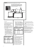
Страница 31: ...is wired for blower speeds required for normal operation as shown If additional blower speed taps are available leads connected to M1 M2 and M3 on the electronic control speeds may be changed if neces...
Страница 32: ...asured temperature rise to the approved temperature rise range listed on the furnace name plate See Figure 25 If the measured temperature rise is above the approved range either the air flow is too lo...
Страница 33: ...2 1611 760 1572 741 1474 695 1433 676 1319 622 LOW RED 1 840 396 717 338 634 299 545 257 495 233 400 188 MED LO YELLOW 2 992 468 945 446 909 429 831 392 783 369 702 331 MED PURPLE 3 1214 573 1176 555...
Страница 34: ...ll out condition the switch will shut the furnace down Switches for the GPT furnaces are located on either side of the burner cover plate and just above the burners on the blower divider panel The GLT...
Страница 35: ...1 241 2 125 150 223 4 X 25 153 4 X 25 1 FILTER ROD 45 24095 01 IMPORTANT Do not operate the system for extended periods without filters A portion of the dust entrained in the air may temporarily lodg...
Страница 36: ...AE 60520 01 FILTER SUPPORT ANGLE SEE ANGLE DETAIL AE 61883 01 FILTER ROD SUPPORT ANGLE AE 60520 01 FILTER SUPPORT ANGLE AE 61883 01 CUT OUT AND DRILL DETAIL FILTER AND ROD ASSEMBLY ROD FILTER SUPPORT...
Страница 37: ...XCHANGER CAN CAUSE TOXIC FUMES TO ENTER THE HOME RESULTING IN CARBON MONOXIDE POISONING OR DEATH THE VENT PIPE OR HEAT EXCHANGER MUST BE REPLACED IF THEY LEAK IMPORTANT It is recommended that at the b...
Страница 38: ...Did a limit open during ignition trial If yes go to D Check voltage between HEAT and COMMON on IFC Check wires connections and continuity between IFC and IBM Check IBM capacitor Check IBM CHECK groun...
Страница 39: ...39 FIGURE 31 FOR MODELS WITH UT ELECTRONIC CONTROLS 1028 928 INTEGRATED FURNACE CONTROL AND DIRECT SPARK IGNITION...
Страница 40: ...CM 0510 40...