5-565.1
46
L
1.5
1.5
H
W
V
I
Airflow
Direction
TOP VIEW
FL
FH
Airflow Direction
S
1.8
1.8
2.25
2.25
Supply Water Line
Connection turned 90° in
direction of airflow
Return Water Line
Connection turned 90° in
direction of airflow
Coil for Right Hand Units
(Digit 9 = R)
Headers on opposite side for
Left Hand Units
FRONT VIEW
SIDE VIEW
dimensions - cooling coils
model size
fH
H
s
v
fl
i
l
supply line return line
75
27
30
1.5
1.5
16.25
25.50
19.25
1.50 MPT
1.50 MPT
100/125
27
30
1.5
1.5
19.50
28.75
22.50
1.50 MPT
1.50 MPT
150/175
27
30
1.5
1.5
23.00
32.25
26.00
1.50 MPT
1.50 MPT
200/225
33
34.5
0.5
1
25.50
34.75
28.50
1.50 MPT
1.50 MPT
250/300
33
34.5
0.5
1
28.50
37.75
31.50
1.50 MPT
1.50 MPT
350/400
33
34.5
0.5
1
40.25
49.50
43.25
1.50 MPT
1.50 MPT
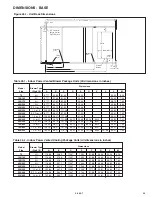
table 46.2 - chilled Water coil dimensions
figure 46.2 - chilled Water coil drawing (all dimensions in inches)
dX - single circuit
dX - dual circuit
model
cooling
suction
liquid
suction
liquid
size
mBH
line (Qty) line (Qty)
line (Qty) line (Qty)
75
All
27.5 30.5
1.5
18
25
21
(1) 1.625 (1) 1.375 16.25 26.5 19.25 (2) 1.625
(2) 0.875
100/125
All
27.5 30.5
1.5
21
28
24
(1) 1.625 (1) 1.375 19.5 29.75 22.5 (2) 1.625
(2) 0.875
150/175
All
27.5 30.5
1.5
24
31
27
(1) 1.625 (1) 1.375
23
33.25 26.0 (2) 1.625
(2) 0.875
table 46.1 - dX coil dimensions
fH
H
s
fl
i
l
200/225
250/300
350/400
Below 185
MBH
185 MBH
& Up
fl
i
l
25.5 35.75 28.5 (2) 1.625
(2) 0.875
28.5 38.75 31.5 (2) 1.625
(2) 0.875
40.25 50.5 43.25 (2) 1.625
(2) 0.875
32.5 34.5
0.5
27
34
30
(1) 1.625 (1) 1.375
32.5 34.5
0.5
27
34.5
30
(1) 2.125 (1) 1.375
32.5 34.5
0.5
30
37
33
(1) 1.625 (1) 1.375
32.5 34.5
0.5
30
37.5
33
(1) 2.125 (1) 1.375
32.5 34.5
0.5
42
49
45
(1) 1.625 (1) 1.375
32.5 34.5
0.5
42
49.5
45
(1) 2.125 (1) 1.375
Below 185
MBH
185 MBH
& Up
Below 185
MBH
185 MBH
& Up
L
1.5
1.5
H
W
1.5
I
Airflow
Direction
TOP VIEW
FL
FH
Airflow Direction
S
Coil for Right Hand Units
(Digit 9 = R)
Headers on opposite
side for Left Hand Units
Suction Line Connections in direction
of airflow
(Second Inlet on Dual Circuit Coils)
Distributor Inlet (Liquid
Line) Connection(s)
(Second Inlet on Dual
Circuit Coils)
FRONT VIEW
SIDE VIEW
figure 46.1 - dX coil drawing (all dimensions in inches)
rows 2 3 4
6
W 7.5 6 7.5 10
rows 4
6
W 7.5 10


