


13-42
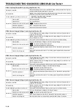
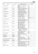
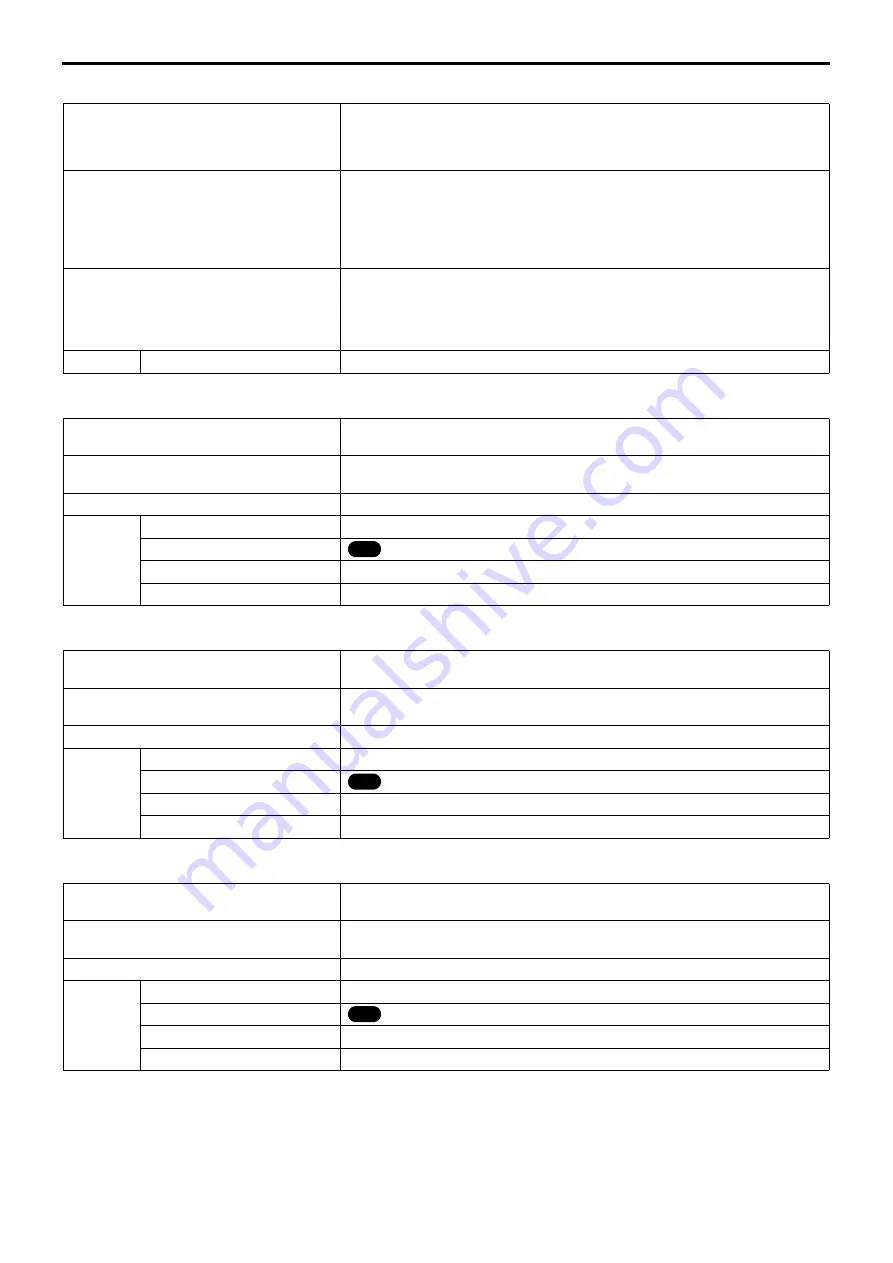
P0605: ECU System (Hardware) (warning lamp flashes: 33)
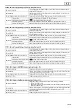
P1171: Q Adjustment Resistor (Low) (warning lamp flashes: 34)
P1172: Q Adjustment Resistor (High) (warning lamp flashes: 34)
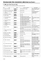
P1176: PTO Adjustment Resistor (Low) (warning lamp flashes: 62)
Generation condition
Diagnosis code is generated under either of the following conditions.
(1) Power supply circuit or power supply in electronic control unit is abnormal.
(2) Devices (analog-digital converter, IC for driving injector or timer IC) in electron-
ic control unit or CPU gate array communication are abnormal.
Recoverability
•
In the case of above problem (1)
•
System recovers if power supply circuit or power supply in electronic con-
trol unit becomes normal.
•
In the case of above problem (2)
•
System recovers (power is re-supplied to electronic control unit) if signal
becomes normal when starter switch is turned OFF
→
ON.
Control effected by electronic control unit
•
In the case of above problem (1)
•
Engine warning lamp (orange) display
•
In the case of above problem (2)
•
Engine warning lamp (red) display
•
Engine is stopped.
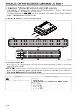
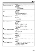
Inspection
Other
Replace the engine electronic control unit.
Generation condition
Fuel injection rate adjustment resistor voltage remains less than 0.2 V for 3 sec-
onds.
Recoverability
System recovers when fuel injection rate adjustment resistor voltage remains 0.2
V or more for 1 second.
Control effected by electronic control unit
Control is effected using backup value (No. 1). (Output is slightly reduced.)
Inspection
Service data
33: Q Adjustment Resistor No.
Electronic control unit connector
: Fuel injection rate adjustment resistor
Electrical equipment
#828: Fuel injection rate adjustment resistor
Electric circuit diagram
Fuel injection rate adjustment resistor system
Generation condition
Fuel injection rate adjustment resistor voltage remains higher than 4.8 V for 3
seconds.
Recoverability
System recovers when fuel injection rate adjustment resistor voltage remains 4.8
V or less for 1 second.
Control effected by electronic control unit
Control is effected using backup value (No. 1). (Output is slightly reduced.)
Inspection
Service data
33: Q Adjustment Resistor No.
Electronic control unit connector
: Fuel injection rate adjustment resistor
Electrical equipment
#828: Fuel injection rate adjustment resistor
Electric circuit diagram
Fuel injection rate adjustment resistor system
Generation condition
Power take-off resistor voltage remains less than 0.2 V for 3 seconds when gov-
ernor control switch is ON.
Recoverability
System recovers when power take-off resistor voltage remains 0.2 V or more for
1 second when governor control switch is ON.
Control effected by electronic control unit
Control is effected using backup value (not resistor).
Inspection
Service data
36: PTO Adjustment Resistor No.
Electronic control unit connector
: Power take-off resistor
Electrical equipment
#828: Power take-off resistor
Electric circuit diagram
Power take-off resistor system
12
12
13
TROUBLESHOOTING <DIAGNOSIS USING Multi-Use Tester>
Содержание 6M70
Страница 29: ...M E M O 11 19 11 ...
Страница 35: ...M E M O 11 25 11 ...
Страница 36: ...11 26 MITSUBISHI 6M70 ROCKER COVER ROCKER AND SHAFT ...
Страница 40: ...11 30 MITSUBISHI 6M70 CAMSHAFT AND ROCKER CASE ...
Страница 47: ...M E M O 11 37 11 ...
Страница 48: ...11 38 MITSUBISHI 6M70 CYLINDER HEAD AND VALVE MECHANISM ...
Страница 63: ...M E M O 11 53 11 ...
Страница 71: ...M E M O 11 61 11 ...
Страница 77: ...M E M O 11 67 11 ...
Страница 81: ...M E M O 11 71 11 ...
Страница 98: ...11 88 MITSUBISHI 6M70 CRANKSHAFT AND CRANKCASE ...
Страница 127: ...M E M O 12 21 12 ...
Страница 129: ...M E M O 12 23 12 ...
Страница 135: ...M E M O 13 3 13 ...
Страница 138: ...13 6 1 1 Mitsubishi 6M70 Supply pump STRUCTURE AND OPERATION ...
Страница 150: ...13 18 10 Electronic control unit connection diagram STRUCTURE AND OPERATION ...
Страница 151: ...13 13 19 ...
Страница 155: ...M E M O 13 23 13 ...
Страница 185: ...M E M O 13 53 13 ...
Страница 189: ...M E M O 13 57 13 ...
Страница 205: ...M E M O 13 73 13 ...
Страница 211: ...M E M O 13 79 13 ...
Страница 215: ...M E M O 13 83 13 ...
Страница 219: ...M E M O 13 87 13 ...
Страница 225: ...M E M O 13 93 13 ...
Страница 226: ...13 94 INSTALLED LOCATIONS OF PARTS ...
Страница 227: ...13 13 95 ...
Страница 228: ...13 96 INSTALLED LOCATIONS OF PARTS ...
Страница 229: ...13 13 97 ...
Страница 230: ...13 98 INSTALLED LOCATIONS OF PARTS ...
Страница 231: ...13 13 99 ...
Страница 232: ...13 100 MITSUBISHI 6M70 INSTALLED LOCATIONS OF PARTS ...
Страница 233: ...13 13 101 ...
Страница 234: ...13 102 ELECTRIC CIRCUIT DIAGRAM ...
Страница 235: ...13 13 103 ...
Страница 236: ...13 104 ELECTRIC CIRCUIT DIAGRAM ...
Страница 237: ...13 13 105 ...
Страница 238: ...13 106 ELECTRIC CIRCUIT DIAGRAM ...
Страница 241: ...14 14 3 1 Mitsubishi 6M70 Cooling System Flow of Coolant STRUCTURE AND OPERATION ...
Страница 252: ...14 14 Periphery of Engine DISCONNECTION AND CONNECTION OF HOSES AND PIPES ...
Страница 271: ...M E M O 14 33 14 ...
Страница 286: ...M E M O 15 13 15 ...
Страница 295: ...15 22 7 Installed Locations of Parts TURBOCHARGER CONTROL SYSTEM ...
Страница 296: ...15 15 23 ...
Страница 297: ...15 24 TURBOCHARGER CONTROL SYSTEM ...
Страница 298: ...15 15 25 ...
Страница 299: ...15 26 TURBOCHARGER CONTROL SYSTEM ...
Страница 300: ...15 15 27 ...
Страница 301: ...15 28 TURBOCHARGER CONTROL SYSTEM ...
Страница 302: ...M E M O 15 29 15 ...
Страница 303: ...15 30 8 Electric Circuit Diagram TURBOCHARGER CONTROL SYSTEM ...
Страница 304: ...15 15 31 ...
Страница 305: ...15 32 TURBOCHARGER CONTROL SYSTEM ...
Страница 306: ...M E M O 15 33 15 ...
Страница 330: ...M E M O 15 57 15 ...
Страница 340: ...17 6 1 3 Electronic control unit connection diagram STRUCTURE AND OPERATION ...
Страница 343: ...M E M O 17 9 17 ...
Страница 351: ...M E M O 17 17 17 ...
Страница 352: ...17 18 8 Installed Locations of Parts EXHAUST GAS RECIRCULATION SYSTEM ...
Страница 353: ...17 17 19 ...
Страница 354: ...17 20 EXHAUST GAS RECIRCULATION SYSTEM ...
Страница 355: ...17 17 21 ...
Страница 356: ...17 22 EXHAUST GAS RECIRCULATION SYSTEM ...
Страница 357: ...17 17 23 ...
Страница 358: ...17 24 9 Electric Circuit Diagram EXHAUST GAS RECIRCULATION SYSTEM ...
Страница 359: ...17 17 25 ...
Страница 360: ...17 26 MITSUBISHI 6M70 EGR VALVE EGR MAGNETIC VALVE EGR PIPE AND EGR COOLER ...