


14
14-9
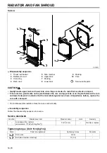
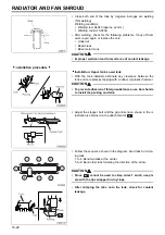
3. Coolant Replacement and Cleaning of Cooling System
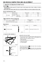
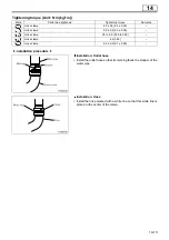
Tightening torque (Unit: N·m {kgf·m})
•
Using the radiator for extended periods of time without cleaning can increase chance of rust and scale formation,
which may cause engine overheating. The cooling system must be cleaned periodically.
Use a coolant containing the FUSO DIESEL LONGLIFE COOLANT additive and soft water in the specified pro-
portions. (See the Owner’s Handbook for instructions on the use of the additive.)
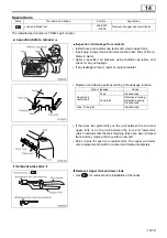
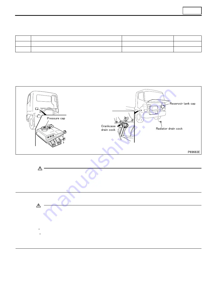
3.1 Draining of coolant
•
Before draining the coolant, loosen the pressure cap to reduce the pressure in the cooling system. Remember to
drain the coolant out of the reservoir tank as well.
WARNING
• Drain the coolant only after it has cooled sufficiently to avoid getting scalded.
• Opening the pressure cap while the coolant temperature is still high can cause hot coolant to spray
out. Cover the pressure cap with a cloth, and loosen it slowly to let the pressure out before opening it
fully.
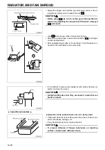
3.2 Cleaning procedure
CAUTION
• Water used for flushing the cooling system must be soft water that has a property meeting the require-
ments indicated below. Using hard water will cause scale and rust to form in the system.
Required properties of soft water
Total hardness .......................... 300 ppm or less
Sulfate SO .............................. 100 ppm or less
Chloride CI ............................. 100 ppm or less
Total dissolved solids .............. 500 ppm or less
pH .............................................. 6 to 8
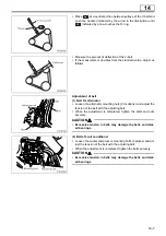
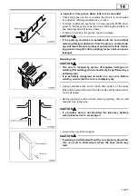
•
Keep the coolant temperature at approximately 90
°
C so that the thermostat valve remains open and coolant con-
tinues to circulate in the radiator.
•
For the sake of convenience you can raise the coolant temperature quickly by covering the front of the radiator
with corrugated cardboard or something similar.
•
In cases where a great amount of rust has accumulated it is common for the radiator to leak as a result of clean-
ing. Conduct a through check for leakage after cleaning.
•
Select an appropriate cleaning method according to the condition of the cooling system as shown below.
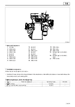
Mark
Parts to be tightened
Tightening torque
Remarks
–
Radiator drain cock
2.0 {0.2}
–
–
Crankcase drain cock
37 {3.8}
–
4
Содержание 6M70
Страница 29: ...M E M O 11 19 11 ...
Страница 35: ...M E M O 11 25 11 ...
Страница 36: ...11 26 MITSUBISHI 6M70 ROCKER COVER ROCKER AND SHAFT ...
Страница 40: ...11 30 MITSUBISHI 6M70 CAMSHAFT AND ROCKER CASE ...
Страница 47: ...M E M O 11 37 11 ...
Страница 48: ...11 38 MITSUBISHI 6M70 CYLINDER HEAD AND VALVE MECHANISM ...
Страница 63: ...M E M O 11 53 11 ...
Страница 71: ...M E M O 11 61 11 ...
Страница 77: ...M E M O 11 67 11 ...
Страница 81: ...M E M O 11 71 11 ...
Страница 98: ...11 88 MITSUBISHI 6M70 CRANKSHAFT AND CRANKCASE ...
Страница 127: ...M E M O 12 21 12 ...
Страница 129: ...M E M O 12 23 12 ...
Страница 135: ...M E M O 13 3 13 ...
Страница 138: ...13 6 1 1 Mitsubishi 6M70 Supply pump STRUCTURE AND OPERATION ...
Страница 150: ...13 18 10 Electronic control unit connection diagram STRUCTURE AND OPERATION ...
Страница 151: ...13 13 19 ...
Страница 155: ...M E M O 13 23 13 ...
Страница 185: ...M E M O 13 53 13 ...
Страница 189: ...M E M O 13 57 13 ...
Страница 205: ...M E M O 13 73 13 ...
Страница 211: ...M E M O 13 79 13 ...
Страница 215: ...M E M O 13 83 13 ...
Страница 219: ...M E M O 13 87 13 ...
Страница 225: ...M E M O 13 93 13 ...
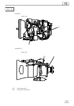
Страница 226: ...13 94 INSTALLED LOCATIONS OF PARTS ...
Страница 227: ...13 13 95 ...
Страница 228: ...13 96 INSTALLED LOCATIONS OF PARTS ...
Страница 229: ...13 13 97 ...
Страница 230: ...13 98 INSTALLED LOCATIONS OF PARTS ...
Страница 231: ...13 13 99 ...
Страница 232: ...13 100 MITSUBISHI 6M70 INSTALLED LOCATIONS OF PARTS ...
Страница 233: ...13 13 101 ...
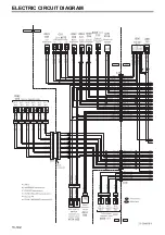
Страница 234: ...13 102 ELECTRIC CIRCUIT DIAGRAM ...
Страница 235: ...13 13 103 ...
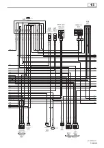
Страница 236: ...13 104 ELECTRIC CIRCUIT DIAGRAM ...
Страница 237: ...13 13 105 ...
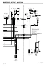
Страница 238: ...13 106 ELECTRIC CIRCUIT DIAGRAM ...
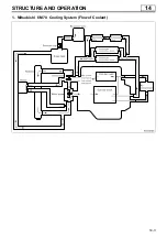
Страница 241: ...14 14 3 1 Mitsubishi 6M70 Cooling System Flow of Coolant STRUCTURE AND OPERATION ...
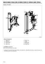
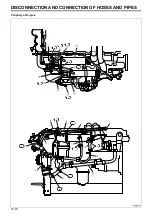
Страница 252: ...14 14 Periphery of Engine DISCONNECTION AND CONNECTION OF HOSES AND PIPES ...
Страница 271: ...M E M O 14 33 14 ...
Страница 286: ...M E M O 15 13 15 ...
Страница 295: ...15 22 7 Installed Locations of Parts TURBOCHARGER CONTROL SYSTEM ...
Страница 296: ...15 15 23 ...
Страница 297: ...15 24 TURBOCHARGER CONTROL SYSTEM ...
Страница 298: ...15 15 25 ...
Страница 299: ...15 26 TURBOCHARGER CONTROL SYSTEM ...
Страница 300: ...15 15 27 ...
Страница 301: ...15 28 TURBOCHARGER CONTROL SYSTEM ...
Страница 302: ...M E M O 15 29 15 ...
Страница 303: ...15 30 8 Electric Circuit Diagram TURBOCHARGER CONTROL SYSTEM ...
Страница 304: ...15 15 31 ...
Страница 305: ...15 32 TURBOCHARGER CONTROL SYSTEM ...
Страница 306: ...M E M O 15 33 15 ...
Страница 330: ...M E M O 15 57 15 ...
Страница 340: ...17 6 1 3 Electronic control unit connection diagram STRUCTURE AND OPERATION ...
Страница 343: ...M E M O 17 9 17 ...
Страница 351: ...M E M O 17 17 17 ...
Страница 352: ...17 18 8 Installed Locations of Parts EXHAUST GAS RECIRCULATION SYSTEM ...
Страница 353: ...17 17 19 ...
Страница 354: ...17 20 EXHAUST GAS RECIRCULATION SYSTEM ...
Страница 355: ...17 17 21 ...
Страница 356: ...17 22 EXHAUST GAS RECIRCULATION SYSTEM ...
Страница 357: ...17 17 23 ...
Страница 358: ...17 24 9 Electric Circuit Diagram EXHAUST GAS RECIRCULATION SYSTEM ...
Страница 359: ...17 17 25 ...
Страница 360: ...17 26 MITSUBISHI 6M70 EGR VALVE EGR MAGNETIC VALVE EGR PIPE AND EGR COOLER ...